Hydroponic Pump Sizing: Calculating True GPH and Head Loss

Table of Contents
- The Physics of Total Dynamic Head (TDH)
- Static Head and Vertical Lift Mechanics
- Pipe Friction Loss and the Hazen-Williams Equation
- Fitting Losses: The Equivalent Length Method
- Calculating TDH: Engineering Scenarios
- Interpreting Pump Performance Curves
- Sizing Margins, Fluid Viscosity, and Biofilm
- Troubleshooting Flow Issues, Air Locks, and Cavitation
- Frequently Asked Questions
Disclosure: MistCulture summarizes verified product specs, engineering data, and community feedback. We may earn an affiliate commission if you purchase through our links. Regulations vary by location; this content is for educational purposes only.
Every hydroponic grower has experienced the moment of truth: a pump rated at 400 GPH delivers barely 150 GPH in an actual system. The gap between theoretical pump capacity and real-world delivered flow is a direct consequence of physical realities that manufacturers rarely emphasize on retail packaging. Vertical head height and pipe friction loss consume pump energy in predictable ways that dramatically reduce the volume of nutrient solution reaching your plants.
This guide details the complete engineering framework for calculating actual pump performance across various hydroponic layouts. Whether sizing a pump for a residential nutrient film technique setup or engineering a multi-level commercial vertical farm, understanding fluid dynamics prevents the common pitfalls of undersizing or oversizing your water delivery infrastructure.
The Physics of Total Dynamic Head (TDH)
Total Dynamic Head (TDH) represents the total equivalent height that a fluid is to be pumped, taking into account all vertical elevation changes and the friction generated by the plumbing network.
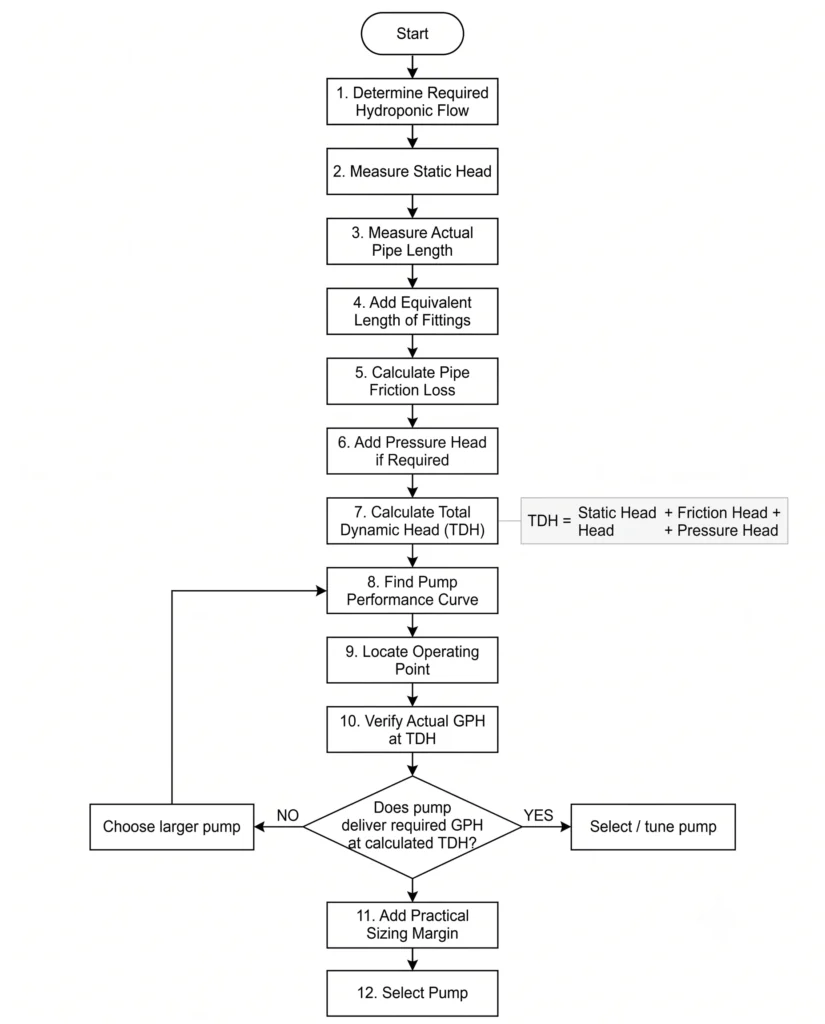
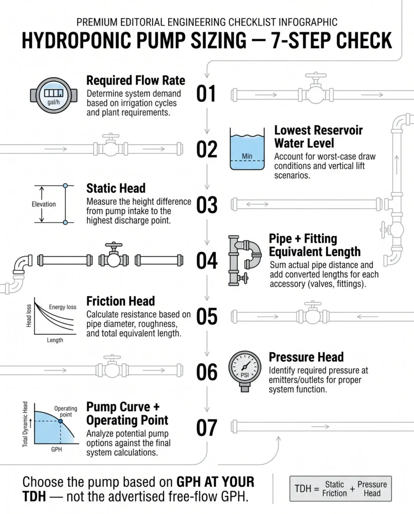
Water does not move through pipes freely. Every millimeter of pipe wall, every directional change, and every inch of vertical lift extracts kinetic energy from the fluid. To select the correct pump, you must calculate the Total Dynamic Head (TDH) of your system. TDH is the sum of three distinct components:
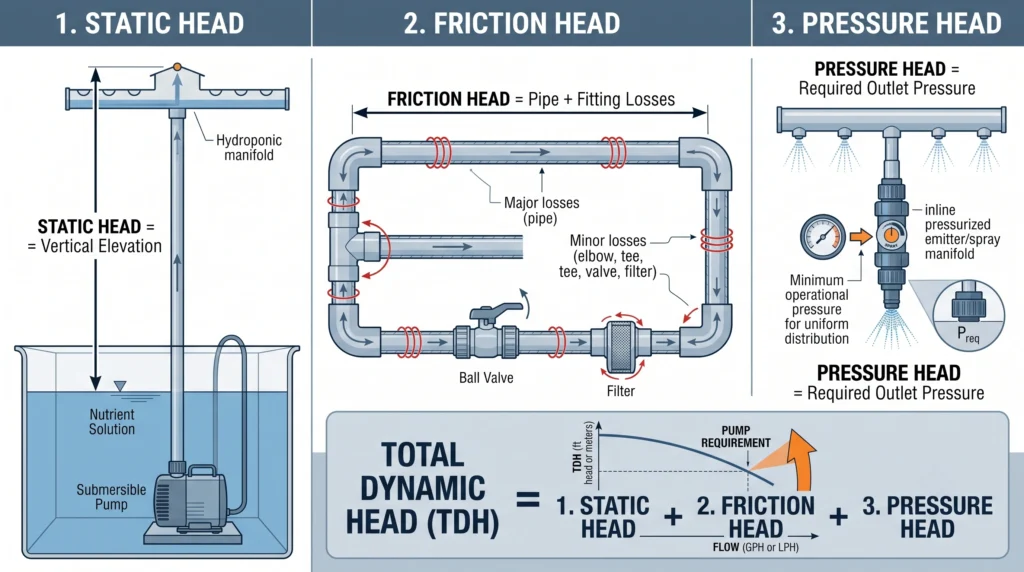
TDH = Static Head + Friction Head + Pressure Head
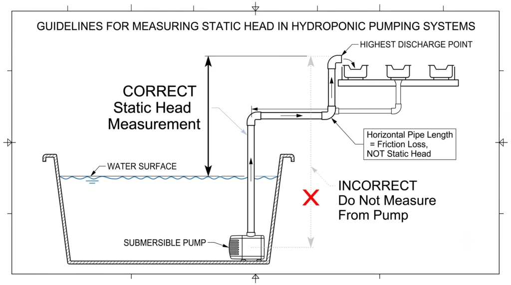
Static Head is the net vertical distance the water must be lifted. It is measured from the surface of the water in the reservoir to the highest point of discharge.
Friction Head is the energy lost due to water rubbing against the interior walls of pipes and fittings.
Pressure Head is the operating pressure required at the delivery point. In most low-pressure hydroponic systems like NFT or Dutch buckets, pressure head is zero because the water discharges freely into the atmosphere. For aeroponic misting systems, pressure head becomes a major factor.
In standard hydroponic designs, calculations focus heavily on Static Head and Friction Head. Ignoring either component guarantees poor system performance. If you install a pump capable of exactly 5 feet of static head in a 5-foot tall vertical tower, zero water will exit the top because the friction inside the delivery tube consumes the remaining pump energy before the water reaches the discharge point.
You can reference our baseline hydroponic pump sizing guide for general pump selection parameters, but determining specific TDH requires detailed mathematical calculation.
Static Head and Vertical Lift Mechanics
Vertical elevation change consumes energy at a rate of 0.433 PSI per vertical foot of water column. Pump performance degrades exponentially as elevation increases.
Static Head is the most visible hurdle your pump must overcome. It is critical to measure static head correctly. It is not the total length of the pipe. If your pipe runs horizontally for 50 feet and then vertically for 3 feet, the static head is exactly 3 feet. The horizontal run contributes exclusively to friction head, not static head.
Furthermore, static head is measured from the surface of the water in the reservoir, not from the location of the submersible pump sitting at the bottom of the tank. As the water level in the reservoir drops, the static head increases. For systems with deep reservoirs, a pump might deliver adequate flow when the tank is full but fail to push water to the highest tier when the tank is near empty. Calculate static head based on the lowest expected water level in your reservoir to guarantee consistent delivery.
The specific gravity of the fluid also affects the energy required to lift it. Pure water has a specific gravity of 1.0. Heavy nutrient solutions carry dissolved mineral salts, slightly increasing the fluid density. For hobbyists, this density increase is negligible. Commercial operators dosing highly concentrated stock solutions must account for specific gravity when sizing dosing pumps, as viscous fluids demand higher torque. You can learn more about managing nutrient concentrations in our hydroponic nutrients guide.

- HIGH FLOW PERFORMANCE delivers a powerful 1000 gallons per hour capacity, making it the perfect solution for large hydro…
- DURABLE CERAMIC SHAFT features a high-quality impellor design that ensures longevity and resistance to wear, allowing fo…
- VERSATILE SYSTEM SETUP includes multiple hose fittings to accommodate various plumbing sizes, providing the flexibility …
Pipe Friction Loss and the Hazen-Williams Equation
Friction loss accumulates linearly with pipe length and exponentially with fluid velocity. Small pipe diameters generate extreme turbulence and massive flow restrictions.
Friction head is the hidden variable that destroys flow rates in hydroponic networks. As water molecules travel through PVC tubing, they rub against the pipe walls. The resulting friction converts kinetic energy into heat, robbing the fluid of velocity.
Engineers use the Hazen-Williams formula to calculate friction loss in plastic pipes. For standard water delivery in hydroponics, the formula is:
💧 Hazen-Williams Friction Loss Equation
To calculate friction loss through smooth pipes, use the Hazen-Williams formula:
hf = 10.67 × L × (Q / C)1.852 × d-4.8704
- hf = Friction loss in feet of head
- L = Total length of pipe in feet
- Q = Flow rate in Gallons Per Minute (GPM)
- C = Hazen-Williams roughness coefficient (150 for smooth, new Schedule 40 PVC)
- d = Pipe internal diameter in inches
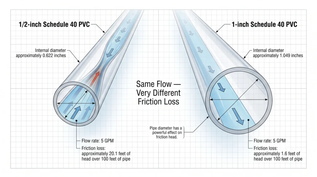
⚡ Key Principle: Pipe diameter has a massive impact on friction loss due to the high negative exponent (d-4.8704). Doubling pipe diameter reduces friction loss by more than 20-fold.
📊 Comparison Example: 5 GPM (300 GPH) over 100 feet of PVC
1. Using 1/2-inch Schedule 40 PVC (Actual ID = 0.622″)
hf = 10.67 × 100 × (5 / 150)1.852 × (0.622)-4.8704hf = 1,067 × 0.0019 × 9.94- hf = 20.1 feet of head loss (Severe Restriction)
2. Using 1-inch Schedule 40 PVC (Actual ID = 1.049″)
hf = 10.67 × 100 × (5 / 150)1.852 × (1.049)-4.8704hf = 1,067 × 0.0019 × 0.79- hf = 1.6 feet of head loss (Optimal Efficiency)
Increasing the pipe size from 1/2-inch to 1-inch reduces the friction penalty from 20.1 feet down to 1.6 feet. The 1/2-inch pipe chokes the system because 5 GPM forced through a narrow corridor generates extreme velocity and turbulence. To minimize friction, fluid velocity should remain under 5 feet per second. Upsizing the main delivery manifold is the cheapest and most effective method to preserve pump capacity.
For complex network planning, use our hydroponic water efficiency calculator to instantly model flow rates across varying pipe diameters.
Fitting Losses: The Equivalent Length Method
Every directional change forces water molecules to collide, generating turbulence. Fittings are calculated as equivalent lengths of straight pipe added to the total friction math.
Straight pipe calculations are only half the equation. Plumbed systems require elbows to navigate corners, tees to split flow, and valves to isolate zones. Each of these fittings disrupts laminar flow. Water entering a 90-degree elbow crashes into the outer wall of the fitting, creating swirling vortices that consume significant pressure.
Instead of calculating complex fluid dynamics for every joint, engineers use the “Equivalent Length” method. Each fitting is assigned a value representing the length of straight pipe that would generate the exact same amount of friction. You add these equivalent lengths to your actual pipe length before running the Hazen-Williams calculation.
| Fitting Type | 1/2″ PVC Equivalent Length | 3/4″ PVC Equivalent Length | 1″ PVC Equivalent Length |
| 90-Degree Elbow (Standard) | 1.5 feet | 2.0 feet | 2.5 feet |
| 45-Degree Elbow | 0.8 feet | 1.0 feet | 1.5 feet |
| Tee (Flow Through Run) | 1.0 feet | 1.4 feet | 1.7 feet |
| Tee (Flow Through Branch) | 4.0 feet | 5.0 feet | 6.0 feet |
| Ball Valve (Fully Open) | 0.5 feet | 0.5 feet | 0.5 feet |
| Swing Check Valve | 4.0 feet | 5.0 feet | 7.0 feet |
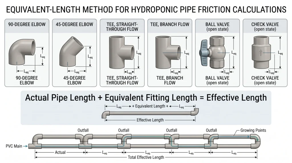
Notice how flow direction through a tee fitting changes the friction penalty drastically. Water moving straight through the horizontal run of a 1/2-inch tee experiences 1.0 foot of equivalent friction. Water forced to make a hard 90-degree turn through the branch of that same tee suffers 4.0 feet of equivalent friction.
System architecture dictates efficiency. A manifold designed with sweep elbows instead of hard 90-degree sharp elbows will deliver higher volumes to the plant canopy. Plumb straight paths for main delivery lines and reserve branch fittings for short lateral feed tubes. For deep dives into system architecture, review our manual on NFT for beginners.
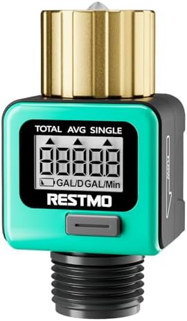
- Pure Brass Inlet & Metal Thread: Durable heavy-duty brass construction ensures exceptional durability and effortless ins…
- Equipped with an easy-to-read LCD screen and one-touch control push button, this water flow meter can easily display and…
- Short press the button to change the mode: Flow Mode: real-time water flow rate; Consumption Mode: last-time water usage…
Calculating TDH: Engineering Scenarios
To solidify these concepts, we will construct mathematical models for two common hydroponic layouts: a residential vertical tower and a commercial low-profile array.
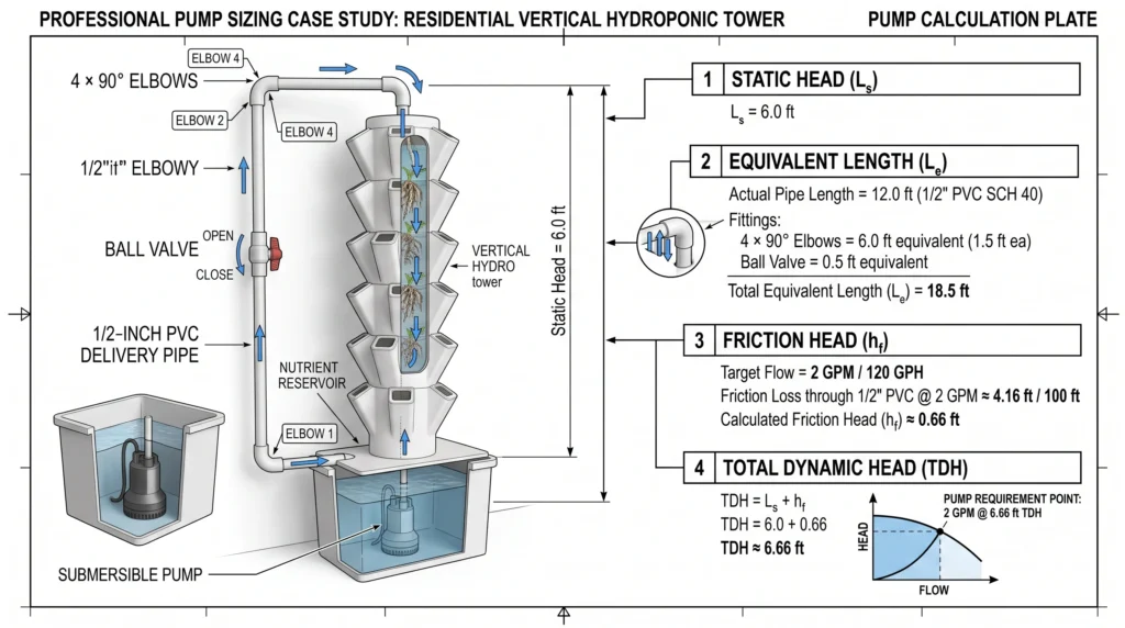
Scenario 1: Residential Vertical Tower
A grower builds a vertical tower. The reservoir sits on the floor. The discharge point at the top of the tower is 6 feet above the lowest water level in the reservoir. The pump pushes water through 12 feet of 1/2-inch PVC tubing. The plumbing requires four 90-degree elbows and one fully open ball valve to regulate flow. The target flow rate is 2 GPM (120 GPH).
Total Dynamic Head (TDH) Calculation
Step 1: Calculate Static Head
- Vertical lift (water surface to discharge point) = 6.0 ft
- Static Head = 6.0 feet
Step 2: Calculate Equivalent Pipe Length
- Actual Pipe Length = 12.0 ft
- Four 90-degree elbows (4 × 1.5 ft) = 6.0 ft
- One Ball Valve = 0.5 ft
- Total Equivalent Length (L) = 18.5 feet
Step 3: Calculate Friction Head
Hazen-Williams formula for 2 GPM through 1/2-inch PVC (ID 0.622):
hf = 10.67 × 18.5 × (2 / 150)1.852 × (0.622)-4.8704hf = 197.39 × 0.00034 × 9.94- Friction Head (hf) = 0.66 feet
Step 4: Calculate Total Dynamic Head (TDH)
TDH = Static Head + Friction HeadTDH = 6.0 + 0.66- Total Dynamic Head (TDH) = 6.66 feet
🎯 Pump Sizing Requirement: Select a pump capable of delivering at least 2 GPM (120 GPH) at 6.66 feet of head.
The pump must overcome 6.66 feet of head to deliver 120 GPH. If you review vertical system designs in our DIY vertical hydroponic tower guide, you will note that static head dominates vertical layouts, while friction remains relatively low due to short pipe runs.
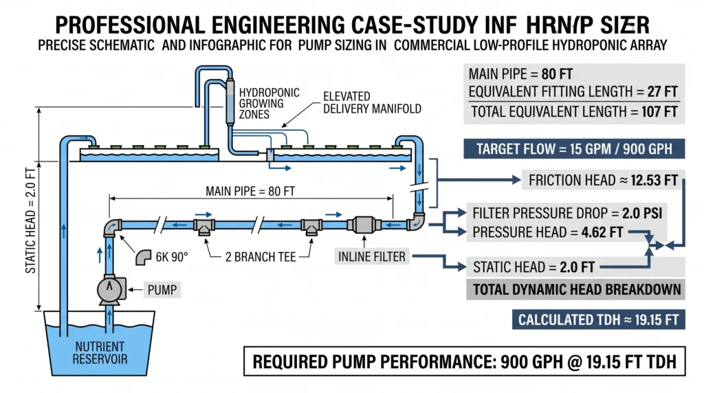
Scenario 2: Commercial Flat Array
A grower builds a horizontal array. The reservoir water level is 2 feet below the delivery manifold. The plumbing network consists of 80 feet of 1-inch PVC main line. The fluid navigates six 90-degree elbows, two tees branching to different zones, and an inline filter that specifies a 2.0 PSI pressure drop at operating flow. The target flow rate is 15 GPM (900 GPH).
Total Dynamic Head (TDH) Calculation
Step 1: Calculate Static Head
- Vertical Lift = 2.0 ft
- Static Head = 2.0 feet
Step 2: Calculate Equivalent Pipe Length
- Actual Pipe Length = 80.0 ft
- Six 1-inch 90° elbows (6 × 2.5 ft) = 15.0 ft
- Two 1-inch Tees (branch flow) (2 × 6.0 ft) = 12.0 ft
- Total Equivalent Length (L) = 107.0 feet
Step 3: Calculate Friction Head
Hazen-Williams formula for 15 GPM through 1-inch PVC (ID 1.049):
hf = 10.67 × 107.0 × (15 / 150)1.852 × (1.049)-4.8704hf = 1141.69 × 0.0139 × 0.79- Friction Head (hf) = 12.53 feet
Step 4: Calculate Filter Pressure Head
Inline filter pressure drop = 2.0 PSI (1 PSI = 2.31 ft of head)
2.0 PSI × 2.31 = 4.62 feet- Pressure Head = 4.62 feet
Step 5: Calculate Total Dynamic Head (TDH)
TDH = Static Head + Friction Head + Pressure HeadTDH = 2.0 + 12.53 + 4.62- Total Dynamic Head (TDH) = 19.15 feet
🎯 Pump Sizing Requirement: In this horizontal array, static head is negligible—friction and pressure drops dictate pump sizing. A pump capable of delivering 900 GPH (15 GPM) at 19.15 feet of head is required.
Interpreting Pump Performance Curves
A pump curve graphs the exact relationship between flow rate (X-axis) and total dynamic head (Y-axis). Sizing relies on finding the intersection of your calculated TDH and the pump’s capability.
Once you establish system TDH, you must evaluate pump documentation. Reputable pump manufacturers provide performance curves. Never rely on the bold print on the front of the box. A pump advertised as “1000 GPH” delivers that volume at exactly zero feet of head. Once attached to plumbing, output plummets.
Examine the performance graph provided by the manufacturer. Locate your calculated TDH on the vertical Y-axis. Draw a horizontal line straight across the graph until you intersect the downward-sloping curve of the pump. Drop a vertical line straight down to the X-axis from that intersection point. This value is your actual delivered GPH.
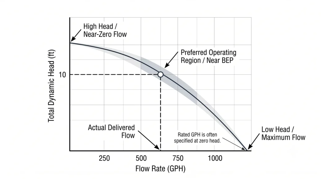
If the delivered GPH at your TDH meets your system requirements, the pump is correctly sized. If the value falls short, you must select the next model up.
Pumps operate with highest efficiency near the middle of their performance curve, an area engineered as the Best Efficiency Point (BEP). Operating a pump at the extreme left of the curve (maximum head, near-zero flow) forces the impeller to churn the same water continuously, transferring motor heat into the nutrient solution. High reservoir temperatures decimate dissolved oxygen levels, accelerating anaerobic bacteria proliferation. You can study temperature mitigation in our hydroponic root rot prevention breakdown. Operating at the extreme right of the curve (maximum flow, near-zero head) can cause motor overload and premature failure. Select a pump where your operating point falls squarely in the middle third of the published curve.
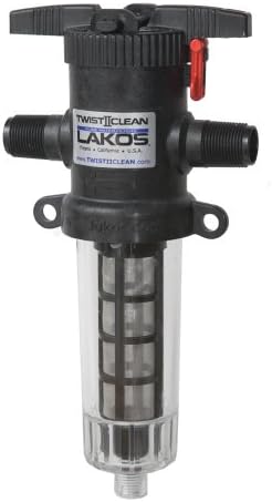
Why it’s necessary: Traps organic debris and undissolved nutrient salts before they enter the irrigation manifold, preventing clogged drip emitters and micro-sprayers.
Sizing Margins, Fluid Viscosity, and Biofilm
Dynamic systems change over time. Pipe roughness increases as biological films accumulate, reducing internal diameters and forcing friction losses higher than original mathematical models predict.
Engineering models assume pristine, smooth pipe walls. Hydroponic systems run organic and inorganic compounds through pipes continuously. Over months of operation, biological slime (biofilm) builds up on the interior walls of PVC tubing. Biofilm is physically rough, altering the Hazen-Williams ‘C’ factor. A smooth PVC pipe with a C-factor of 150 can degrade to a C-factor of 120 within a year of continuous use.
Simultaneously, the accumulation of biofilm reduces the actual internal diameter of the pipe. A 1/2-inch pipe with a 1-millimeter layer of biofilm experiences a severe reduction in cross-sectional area, accelerating fluid velocity and turbulence.
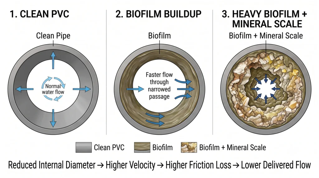
Mineral precipitation also poses a threat. High concentrations of calcium and sulfates can bond and precipitate out of solution, coating pipe walls with rigid scale. Proper nutrient management is required to keep elements dissolved in solution. Ensure you calibrate your dosing regimens according to our hydroponic pH and EC mastery guide.
Because system friction increases as hardware ages, you must build a safety margin into your pump sizing calculations. Standard engineering practice dictates sizing pumps at 125% to 150% of the calculated flow requirement.
If your vertical tower requires exactly 120 GPH at 6.66 feet of head, select a pump that delivers 150 to 180 GPH at that head height. Install a bypass valve on the main delivery line directly above the pump. A bypass valve allows you to bleed off excess flow and redirect it back into the reservoir. This provides two benefits: it allows precise manual tuning of the delivery flow rate, and the bypassed fluid heavily agitates the reservoir, increasing dissolved oxygen levels through surface disruption. For dedicated aeration mechanics, see our breakdown of the best DWC air pumps.
Troubleshooting Flow Issues, Air Locks, and Cavitation
Unexplained flow reductions often stem from poor intake design, trapped air pockets, or vortexing, which starves the pump impeller of adequate fluid supply.
When mathematical calculations check out but physical flow is terrible, the plumbing architecture is usually to blame. Submersible magnetic drive pumps push water effectively but possess zero ability to pull water. They are completely reliant on gravity to feed fluid into the volute chamber.
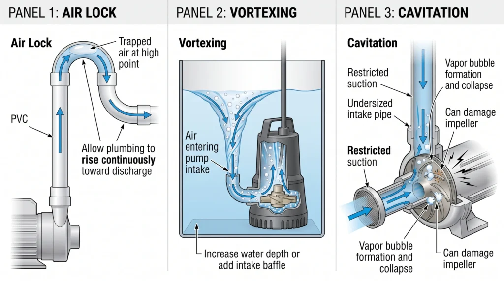
Vortexing occurs when a pump operates in shallow water. The high suction velocity draws water from the surface, creating a visible tornado-like vortex. This vortex pulls air straight into the impeller housing. Air mixed with water causes the impeller to spin erratically, dropping flow rates instantly and generating loud grinding noises. To fix vortexing, increase the reservoir depth or install a plastic baffle plate directly above the pump intake to block surface air from being pulled downward.
Air Locks form when plumbing lines route downward after reaching a high point, creating an inverted U-shape. Air bubbles introduced through system turbulence travel upward and become trapped at the highest point of the inverted U. Because low-pressure hydroponic pumps lack the force to push this air pocket downward against its natural buoyancy, the air pocket creates a massive friction barrier that halts fluid flow entirely. Ensure all delivery manifolds slope gently upward toward the discharge points to allow trapped air to bleed out naturally. For guidance on clean plumbing layouts, refer to our DIY DWC quiet setup manual.
Cavitation is the most destructive force a pump can experience. Cavitation occurs when the Net Positive Suction Head (NPSH) available is lower than the NPSH required by the pump. If the intake line is restricted by a clogged pre-filter or an undersized inlet pipe, the pressure inside the pump casing drops below the vapor pressure of the water. The water physically boils at room temperature, forming microscopic vapor bubbles. When these bubbles pass through the high-pressure side of the impeller, they collapse implosively. The implosions generate shockwaves strong enough to pit metal and shatter plastic impellers.
If your pump sounds like it is pumping gravel, it is cavitating. Immediately shut off the power. Remove any restrictions on the intake side, clean the pump pre-filter, and ensure the intake plumbing is at least one size larger than the discharge plumbing. Never install a valve on the intake side of a centrifugal pump.

- Bates ratchet-type pipe cutter is made of manganese steel with high hardness, good toughness, strength, and durability. …
- The rubber-textured handle is comfortable to use, reliable to hold, and not easy to hurt. A stainless steel buckle is at…
- Bates ratchet-type pipe cutter is perfect for easily cutting through pipes. The triangle design at the edge of the knife…
Frequently Asked Questions
What happens if I heavily oversize my hydroponic pump?
Oversizing a pump without implementing a bypass loop creates severe mechanical and biological issues. A heavily oversized pump pushes fluid at high velocities, scouring plant roots and causing physical damage. Closing a ball valve to choke the flow forces the pump to operate dead-headed against immense pressure. This transfers motor heat into the nutrient solution, raising reservoir temperatures and accelerating root rot. Always use a bypass valve to redirect excess flow back into the reservoir rather than dead-heading the pump.
Does changing pipe thickness from Schedule 40 to Schedule 80 affect flow?
Yes. Schedule 80 PVC has the same outer diameter as Schedule 40 PVC, but the pipe walls are significantly thicker to handle high-pressure industrial applications. Because the walls are thicker, the internal diameter is smaller. A smaller internal diameter increases the fluid velocity and drastically increases friction loss. Always use Schedule 40 or thin-wall Class 200 PVC for low-pressure hydroponic plumbing to maximize internal diameter and reduce friction head.
Can I use flexible vinyl tubing instead of rigid PVC for the entire system?
Flexible vinyl tubing is viable for short runs and branch lines, but it presents structural challenges for main manifolds. Flexible tubing sags between support brackets, creating low spots where sediment accumulates and high spots where air locks form. The internal surface of corrugated or braided flexible tubing is significantly rougher than smooth PVC, generating higher friction losses. Use rigid PVC for long runs and restrict flexible tubing to the final connection points.
How do check valves affect system flow rates?
Check valves prevent nutrient solution from draining backward into the reservoir when the pump shuts off, keeping manifolds primed. However, check valves utilize internal springs or heavy swing-gates to stop backflow. The pump must exert constant pressure to push these mechanisms open. A standard spring-loaded check valve can add the equivalent of 10 to 15 feet of straight pipe friction to your system. Oversize your check valve by one pipe dimension (using reducers to connect it to the main line) to minimize flow restriction.
Why does my pump deliver less flow as my nutrient reservoir empties?
Submersible pumps operate based on the static head measured from the surface of the water to the discharge point. When a 50-gallon reservoir is full, the water level is high, and the static head is relatively low. As the pump drains the reservoir, the water surface drops toward the floor. This increases the total vertical distance the pump must lift the fluid. Sizing calculations must always be based on the lowest operating water level to ensure adequate flow continues as the tank drains.

Continue Your Learning Journey