DIY EC Controller: Building a Closed-Loop Nutrient Dosing System

Table of Contents
A closed-loop EC controller keeps your nutrient strength exactly where you set it. By continuously measuring the electrical conductivity of the solution and automatically dosing a concentrated stock when the EC drifts low, you turn the most tedious daily task in hydroponic crop management into a set-and-forget system.
Building your own DIY EC controller hydroponics setup is a highly achievable weekend engineering project. If you have the basic skills to wire an analog probe, a small peristaltic pump, and a microcontroller like an Arduino or an ESP32, you can assemble a nutrient dosing system that teaches you exactly how commercial controllers process data. This comprehensive guide covers the physics of the control loop, component selection, sensor calibration, software logic, and the mechanical safety interlocks that keep a DIY controller from dumping an entire bottle of nutrient stock into your reservoir.
The Closed-Loop EC Control Concept
Summary: The core architecture of a closed-loop EC controller relies on a continuous sequence: Measure the reservoir conductivity, Compare it against a programmed target, Act by pulsing the dosing pump if the reading is low, and Repeat the cycle after the solution mixes.
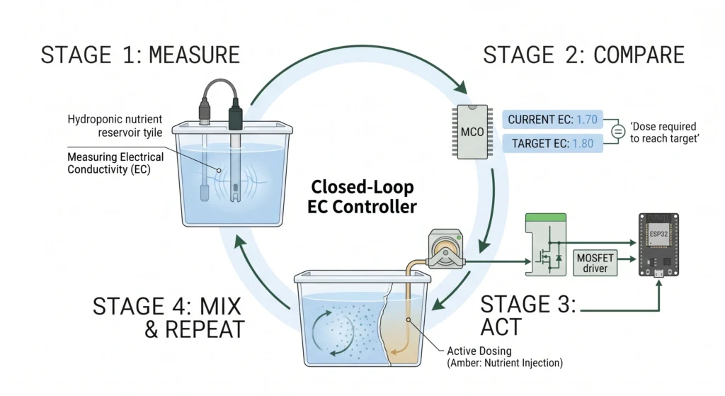
At the center of any automation architecture is the feedback loop. In a closed-loop nutrient dosing system, the controller relies on constant environmental feedback to make real-time decisions. The entire process follows a strict, four-step execution cycle.
Raw Analog Voltage
Target Setpoint
Trigger Pulse Dose
Mix & Re-evaluate
First, an EC (electrical conductivity) probe takes continuous voltage readings across two electrodes submerged in the nutrient solution. Because nutrient salts consist of dissolved ions, a higher concentration of fertilizer allows electrical current to flow more easily through the water. The probe measures this conductance and passes the raw analog data to the microcontroller.
Next, the controller compares that real-time reading against your programmed setpoint. If your target is an EC of 1.8 mS/cm and the current reading is 1.7 mS/cm, the software identifies a deficit.
The controller then acts. When the EC falls below the acceptable deadband threshold, the microcontroller sends a low-voltage logic signal to a relay or MOSFET. This component acts as a high-power switch, instantly turning on a 12V dosing pump that injects a small, precise pulse of concentrated nutrient stock into the reservoir.
Finally, the loop repeats. The controller waits through a programmed mix interval, allowing the water pump to disperse the heavy nutrient salts evenly throughout the reservoir. It re-measures the EC, and if the target band is reached, the dosing halts. The system simply holds that level, guarding against the natural nutrient drift caused by plant uptake and water evaporation. The underlying math for this control loop is identical to the logic used in pH automation. If you are integrating pH control alongside your conductivity setup, refer to our Arduino and Raspberry Pi automated hydroponic dosing system blueprint for the full tandem architecture.
Core Hardware Components for Your DIY Nutrient Doser
Summary: A reliable DIY EC controller requires an isolated analog EC/TDS probe, a capable microcontroller (Arduino Uno, ESP32, or Raspberry Pi Pico), a chemically resistant peristaltic pump, a heavy-duty MOSFET driver, and an independent power supply to separate high-current mechanical loads from sensitive logic boards.
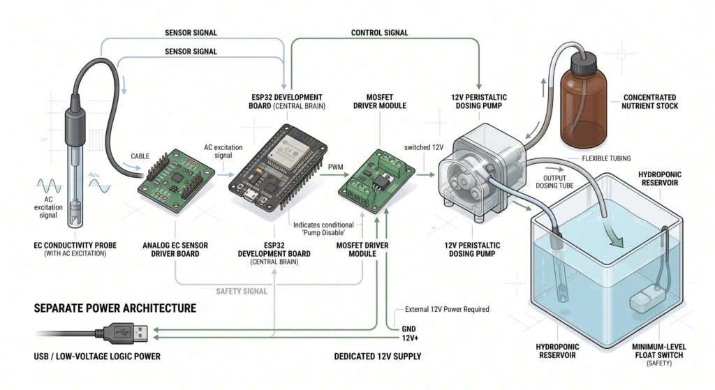
Selecting the right hardware separates a professional-grade DIY nutrient doser from a benchtop experiment that fails under continuous load. The following components form the backbone of the build.
EC/TDS Probe and Driver Board
The conductivity sensor is the sensory organ of the entire build. A quality analog EC/TDS probe paired with an isolated driver board provides readings in the specific range necessary for heavy hydroponic nutrient solutions. Galvanic isolation on the driver board prevents electrical interference. If the EC probe shares the same grounding circuit in the water as a pH probe or a high-voltage submersible pump, ground loops will skew the voltage readings and cause erratic dosing. Commercial-grade gravity-style probes (similar to Bluelab form factors) are easier to calibrate and offer superior longevity. For a deeper understanding of probe maintenance and isolation, read our complete hydroponic sensors guide.

Why it’s necessary: Analog gravity kits include built-in signal conditioning and temperature compensation, allowing your microcontroller to read clean analog voltage without complex external circuitry. The isolation prevents ground loop interference.nKey Spec: 0-3.3V/5V compatible with 1000 to 3000 µS/cm measurement range.
Microcontroller
The brain of the system can be an Arduino Uno, an ESP32, or a Raspberry Pi Pico. The microcontroller’s job is to read the analog voltage from the probe, run the filtering math, apply the hysteresis logic, and switch the pump driver. While an Arduino Uno with its 10-bit analog-to-digital converter (ADC) is perfectly capable of handling basic dosing, an ESP32 development board is often preferred by engineers. The ESP32 features a higher resolution 12-bit ADC for finer sensor reading, and it adds native Wi-Fi capabilities for remote control, data logging, and cloud dashboard integration.

Why it’s necessary: The ESP32 provides massive processing headroom, integrated Wi-Fi for pushing EC data to cloud dashboards, and a 12-bit ADC for highly granular conductivity measurements.nnKey Spec: Dual-core 240MHz processor with integrated 802.11 b/g/n Wi-Fi.
Peristaltic Dosing Pump
Using a standard impeller pump for nutrient concentrates is a rapid path to mechanical failure. Heavy mineral salts will crystallize inside standard pumps and destroy the seals. A peristaltic dosing pump is the safest and most accurate mechanism for handling strong chemicals. It operates by rotating a set of rollers that pinch a flexible tube, pushing the liquid forward. Because the concentrated nutrient stock only touches the inside of the food-safe, chemical-rated tubing, it never makes contact with the pump’s internal mechanics. This design is immune to corrosion and delivers precise, repeatable liquid volumes. Read our breakdown of industrial peristaltic dosing pumps for hydroponic pH buffering to explore the mechanical limits of these units.
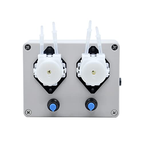
Why it’s necessary: Peristaltic pumps completely isolate corrosive nutrient salts from the pump motor. They offer highly repeatable, low-volume pulse dosing essential for closed-loop stability.nKey Spec: 100 mL/min flow rate with silicone or Santoprene chemical-resistant tubing.
MOSFET Driver and Power Supply
A microcontroller operates on extremely low current (typically 3.3V or 5V logic). It cannot directly power a 12V mechanical pump. The microcontroller’s output pin must trigger a relay or a MOSFET driver board. A logic-level MOSFET acts as an electronic valve: when the ESP32 sends a 3.3V signal to the MOSFET gate, it opens the heavy-duty 12V circuit to spin the pump. You must use a proper 12V power supply dedicated to the pump and the driver, completely separate from the USB power running the microcontroller board to prevent voltage sags from crashing the logic chip.
| From Component | Terminal Pin | To ESP32 Pin | Signal / Function |
|---|---|---|---|
| Analog EC Board | VCC / GND / AOUT | 3V3 / GND / GPIO 34 | Sensor Power & Raw Voltage Input (ADC1) |
| MOSFET Driver Board | SIG / GND / V+ | GPIO 25 / GND / Ext 12V | Pump Gate Trigger (DAC1) & High-Current Supply |
| Dry-Run Float Switch | Terminals 1 / 2 | GPIO 18 / GND | Digital Low-Level Cutoff (Internal Pullup) |
Signal Processing and Software Sketch Logic
Summary: The software running your microcontroller must aggressively filter raw sensor noise using moving averages, execute dosing commands based on strict hysteresis deadbands, and include watchdog timers to gracefully recover from power failures.
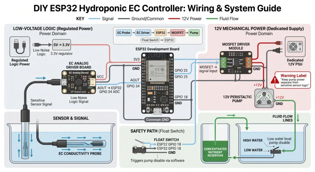
Writing the software sketch is where the hardware components are unified into a functional EC monitoring automation system. The read loop must be engineered to handle real-world physical interference.
Noise Filtering and Moving Averages
Nutrient reservoirs are chaotic environments. Air stones pumping dissolved oxygen into the water create bubbles that will frequently crash into the EC probe electrodes. When a bubble displaces the conductive water between the electrodes, the probe voltage momentarily drops, sending an artificially low EC reading to the microcontroller.
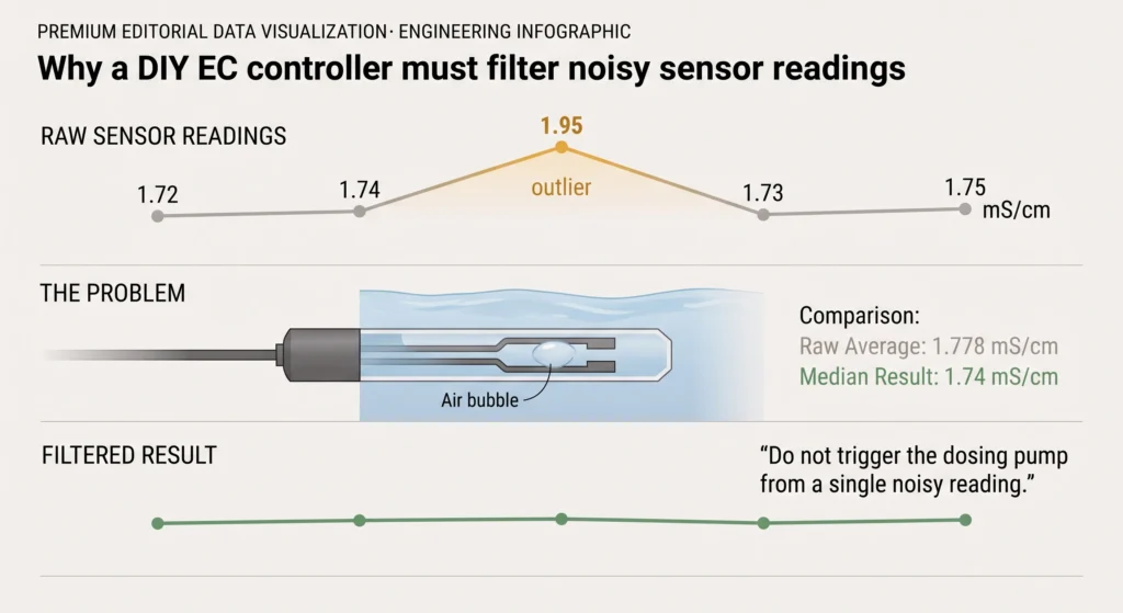
If your software triggers the pump based on a single raw reading, a passing bubble will cause the system to dump unnecessary nutrients into the tank. To prevent this, the code must implement a moving average or median filter. The controller reads the probe rapidly (e.g., once every 100 milliseconds), stores a continuous array of recent samples, and calculates the median.
Our hardware engineering calculations prove why this matters. Consider a raw array of five consecutive EC readings: 1.72, 1.74, 1.95, 1.73, and 1.75 mS/cm. The 1.95 mS/cm reading is an anomaly caused by localized turbulence. A simple mathematical average yields an artificially high 1.778 mS/cm. If your target is 1.75, the controller halts dosing based on false data. By implementing a median filter, the software discards the extreme outliers and isolates the middle value, generating an accurate 1.74 mS/cm reading that reflects the true state of the reservoir.
Dosing Logic and Logging
Once the filtered reading is established, the control logic executes. If the filtered EC is lower than the setpoint minus the deadband, the controller pulses the MOSFET. It then invokes a wait function (the mix interval) before authorizing the next read. Modern sketches running on an ESP32 will format these events with timestamps and push the data payloads to a cloud server or a local SD card. Reviewing your historical EC charts alongside your vapor pressure deficit data provides incredible insight into your crop’s transpiration rates. See our guide on VPD optimization in hydroponics to understand how environmental moisture dictates the concentration at which your controller should be set.
Watchdog Timers
A watchdog timer is a critical safety feature built into microcontrollers. In the event of a power surge or a software crash that hangs the main loop, the watchdog timer will detect that the program has stopped executing. It physically forces the processor to cleanly reboot, re-evaluate the hardware state, and confirm the reservoir levels before authorizing any further pump activity. A controller that hangs while the pump pin is held high will pump blindly until the stock bottle is empty, destroying your crop. The watchdog timer guarantees this cannot happen.
DIY Closed-Loop Control Simulator
Model your control loop, visualize pulse steps, and check overshoot risks before writing software.
Set your physical hardware inputs and chemical boundaries. This tool computes the exact fluid kinetics of each dosing pulse. Verify targets with our hydroponic nutrient calculator.
Below is the live execution path of your microcontroller’s software loops. Click step or play to observe the closed-loop automation cycle.
Embed just the simulator (no extra page elements) on your own site. It loads with a premium standalone design and retains the MistCulture copyright.
Powered by MistCulture
Calibration Protocols and Deadband Hysteresis
Summary: Accurate calibration using a 1413 µS/cm standard solution ensures measurement fidelity. Applying mathematical hysteresis (a deadband of ~0.05 to 0.1 EC) and short pulse dosing durations prevents the control loop from overshooting the target and repeatedly toggling the pump.
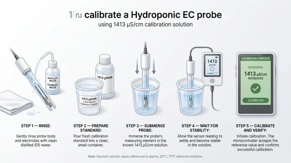
A drifting probe turns a highly engineered smart controller into a hazard. You must calibrate the EC probe with a known standard before the first run and conduct routine maintenance checks monthly.
The industry standard calibration fluid for hydroponic EC probes is 1413 µS/cm. This equates to an EC of 1.413 mS/cm, putting the calibration point perfectly inside the target range of most vegetative and fruiting crops. By taking a voltage reading while the probe is submerged in the 1413 µS/cm solution, you set the slope of the calibration curve in your software. If you need to map out your target parts-per-million against specific crop phases, use our hydroponic nutrient calculator to set your precise baseline.
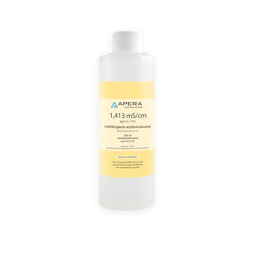
Why it’s necessary: Conductivity measurements rely on precise baseline voltages. Without a factory-certified 1413 µS/cm standard solution, your controller’s math will drift, causing either heavy under-feeding or catastrophic nutrient burn.nKey Spec: NIST-traceable 1413 µS/cm (1.41 mS/cm) fluid.
Understanding Deadbands and Hysteresis
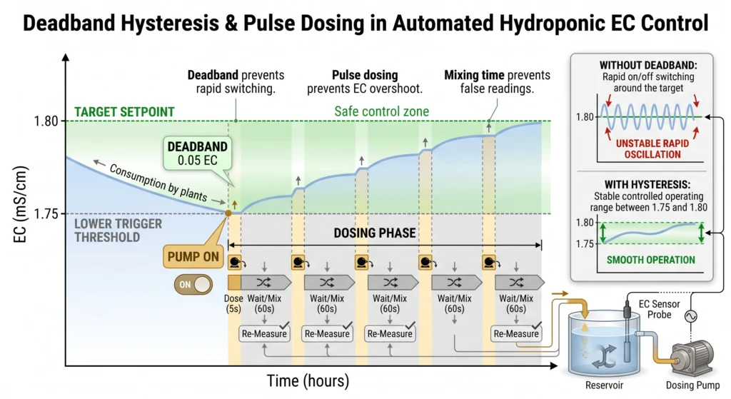
Hysteresis is the intentional lag introduced into the control loop to stop the “machine-gun effect.” Without a deadband, if your target is 1.80 EC, the pump triggers at 1.79. A drop of nutrient pushes the reading to 1.80, and the pump shuts off. One second later, the reading drops to 1.79, and the pump triggers again. The relay will click on and off hundreds of times an hour, quickly destroying the mechanical switch.
By programming a deadband of 0.05 EC, the logic changes. The controller will now only turn the pump on when the reading drops to 1.75 mS/cm (Setpoint 1.80 – Deadband 0.05). Once triggered, it will slowly pulse the pump until the reading climbs all the way back up to 1.80 mS/cm before shutting off. The system will then rest until crop uptake brings the concentration back down to 1.75.
Pulse Dosing Mechanics
Pulse dosing beats continuous dosing every time. When concentrated fertilizer drops into water, it takes time for the submersible circulation pumps to blend the solution homogeneously. If a dosing pump runs continuously until the probe detects the target EC, the unmixed nutrients still traveling across the tank will continue to raise the conductivity long after the pump stops. This guarantees a massive overshoot.
Our hardware calculations demonstrate why short pulses are mandatory. A standard 12V peristaltic pump operating at a flow rate of 100 mL/min will deliver exactly 8.33 mL of stock solution during a 5-second pulse. By programming the system to inject 8.33 mL, pause for 60 seconds of mixing time, and then re-evaluate the EC, the controller creeps up to the setpoint safely without ever over-salting the water. This pulsing strategy mimics the logic found in commercial automated nutrient dosing skids.
Failsafes, Interlocks, and System Safety
Summary: Physical and software interlocks protect the crop from sensor failures. You must interlock the dosing pump against a minimum water level float switch, cap the maximum allowable dosing time, and physically separate concentrated stock lines.
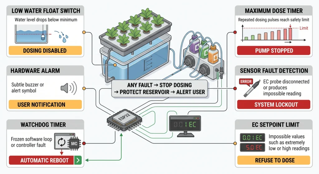
Safety belongs in the core software sketch, not as an afterthought. Never allow a DIY EC controller to dose concentrated stock into a dry or rapidly draining reservoir. If a return pipe bursts and the water level drops, the EC probe will be suspended in the air. The controller will read an EC of zero and assume the tank needs massive amounts of fertilizer. The pump will dump your entire stock bottle into the few remaining inches of water.
Dry-Run Protection and Level Interlocks
To prevent this, physically interlock the dosing loop with a minimum water level switch. If the water drops below the float switch, the microcontroller software must instantly disable the dosing pin and send a hardware alarm. For details on selecting the most reliable level cutoff mechanisms, read our comparison of optical sensors vs float switches for sump tanks.
You must also account for flow dynamics and tank turnover. If your system runs an external mixing loop, ensure your main pumps are sized correctly. Review our hydroponic pump sizing guide for GPH and head loss to verify your mix interval provides adequate dispersion before the probe takes its next reading.
Maximum Dose Timers and Setpoint Caps
Your code should include a maximum dose time limit. If the controller initiates 20 consecutive pulses and the EC reading has not climbed at all, an anomaly has occurred. Either the stock bottle is completely empty, the peristaltic tubing has ruptured, or the probe is fouled with organic matter. The controller should throw an error flag, halt the pump, and trigger a buzzer or send a push notification to your phone.
Add a failsafe setpoint cap. If the measured EC reads absurdly high or impossibly low (e.g., 0.1 EC or 5.0 EC in a vegetative system), the software must refuse to run. It should assume the probe has been unplugged or compromised and default to a hard stop.
Always test your complete control loop in a 5-gallon bucket of clean water before connecting it to a live reservoir containing expensive plants. You can utilize simple aeration devices during the test to simulate reservoir turbulence. Read up on venturi vs air stones in DWC to replicate the heavy bubbling your probe will face in production. The bugs you catch during a bench test are the bugs that will not kill your crop.
Frequently Asked Questions
What is a closed-loop EC controller?
A closed-loop EC controller is an automated system that continuously measures the electrical conductivity of your hydroponic reservoir using a sensor probe. It compares that real-time reading against a programmed target and automatically triggers a dosing pump to add concentrated nutrients when the strength drops, maintaining a perfectly stable environment without manual intervention.
Can I build an EC controller with an Arduino?
Yes. An Arduino Uno or an ESP32 is highly capable of running an automated dosing system. You need the microcontroller, an analog EC probe with a signal driver board, a logic-level MOSFET or relay, and a 12V u003ca href=u0022https://mistculture.com/industrial-peristaltic-dosing-pumps-hydroponic-ph-buffering/u0022u003eperistaltic dosing pumpu003c/au003e. The C++ code requires a simple read-compare-pulse sequence wrapped in a median filter to reject sensor noise.
Why must I use a peristaltic pump for nutrient dosing?
Peristaltic pumps move liquids by using rotating mechanical rollers to pinch and push a flexible tube. Because the liquid is entirely contained within the food-safe tubing, the highly corrosive mineral salts in hydroponic fertilizers never touch the metal gears or the pump motor. This prevents crystallization, seizing, and chemical degradation of the equipment.
How do I stop my DIY nutrient doser from overshooting the target EC?
Overshoot is prevented through pulse dosing and mix intervals. Rather than running the pump continuously until the probe hits the target, the controller pulses the pump for a short duration (e.g., 5 seconds). It then pauses for 60 to 90 seconds to allow the fresh nutrients to circulate through the reservoir. It re-measures the EC only after the water is thoroughly mixed.
Is a DIY EC controller safe to leave unattended with my plants?
Yes, provided you code hard safety interlocks into the software sketch. You must include a deadband hysteresis to prevent relay burnout, a maximum-dose timeout counter to stop the pump if the stock runs dry, and a hardware float switch to disable all dosing if the reservoir water level drops below a safe minimum threshold.
What temperature should my calibration solution be?
Because electrical conductivity is heavily influenced by water temperature, most commercial-grade analog EC driver boards include automatic temperature compensation (ATC) algorithms. However, to guarantee an accurate baseline, your 1413 µS/cm calibration fluid should be as close to standard room temperature (77 F or 25 C) as possible during the calibration procedure.
Conclusion
Automating your nutrient management with a DIY EC controller hydroponics build bridges the gap between residential hobby setups and commercial-grade crop steering. By combining the processing power of an ESP32, the chemical reliability of peristaltic pumps, and the strict mathematical logic of median filters and hysteresis deadbands, you eliminate the daily chore of manual testing and measuring. Your plants receive perfectly stable nutrition, and your reservoir is protected by engineered safety interlocks. If you are preparing to scale this logic across your entire grow space, dive into our comprehensive breakdown of hydroponic grow room engineering, ventilation, and hydraulics to optimize the rest of your facility.

Continue Your Learning Journey