Optical Water Level Sensors vs Float Switches: Engineering Sump Tank Automation

Table of Contents
- The Physics and Mechanics of Mechanical Float Switches
- The Physics and Mechanics of Optical Water Level Sensors
- Sump Tank Drawdown Calculations and Sensor Placement
- Mitigating Environmental Variables: Turbulence and Stilling Wells
- Electrical Integration: Circuits, Relays, and Fail-Safes
- Engineering Redundancy: Two-Tier Fail-Safe Layouts
- Diagnostic Testing and Maintenance Protocols
- Frequently Asked Questions
- Sump Tank Automation Mastery
Disclosure: MistCulture summarizes verified product specs, engineering data, and community feedback. We may earn an affiliate commission if you purchase through our links. Regulations vary by location; this content is for educational purposes only.
Water level control in hydroponic sump tanks dictates the operational safety of the entire recirculating system. A failed level sensor rapidly translates into thousands of dollars in property damage from overflowing reservoirs or total crop loss due to pump dry-run failures. Precision automation relies heavily on the exact mechanism used to detect the liquid boundary layer. This highly technical engineering comparison evaluates the physical mechanics, electrical integration, and specific failure modes of the two dominant technologies utilized in controlled environment agriculture: mechanical float switches and non-contact optical water level sensors.
By breaking down the exact physics of these components, system designers can optimize redundancy, eliminate single points of failure, and accurately size their sumps for peak hydraulic efficiency.
The Physics and Mechanics of Mechanical Float Switches
Sump tank float switches operate on the principle of buoyancy and magnetic field actuation. They utilize a moving physical component to complete an electrical circuit when the water level reaches a predetermined height.
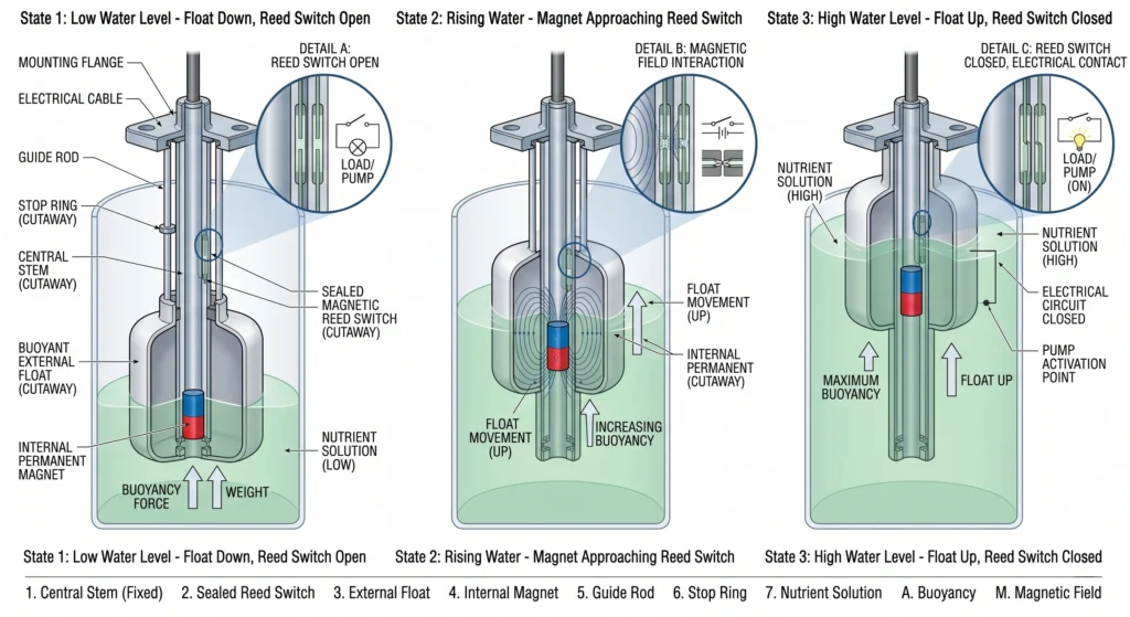
Mechanical float switches are the most ubiquitous level sensors in agricultural automation. The core architecture consists of two primary components: a stationary central stem and a buoyant outer ring (the float) that travels vertically along the stem. The central stem houses a hermetically sealed glass tube containing a magnetic reed switch. The buoyant float houses a permanent magnet.
As the nutrient solution rises within the sump tank, the buoyant force overcomes the gravitational force acting on the float. The specific physics of this interaction dictate that the buoyant force (F_b) equals the density of the fluid (p) multiplied by the displaced volume (V) and the acceleration due to gravity (g). Because the density of a hydroponic nutrient solution is slightly higher than pure water due to dissolved fertilizer salts, the float experiences a marginally stronger upward force in active systems than in plain water tanks.
When the float reaches the exact elevation of the reed switch, the magnetic field generated by the permanent magnet penetrates the glass tube. This magnetic flux pulls two flexible ferromagnetic metal contacts together, closing the circuit. When the water level recedes, gravity pulls the float down, moving the magnetic field away from the reed switch and allowing the contacts to spring apart, breaking the circuit.
Failure Modes of Mechanical Systems
While simple and cost-effective, mechanical switches fail in highly predictable patterns based on their physical environment. The movement of the float introduces mechanical friction against the central stem. In a hydroponic sump tank, this environment is saturated with dissolved solids and organic matter.
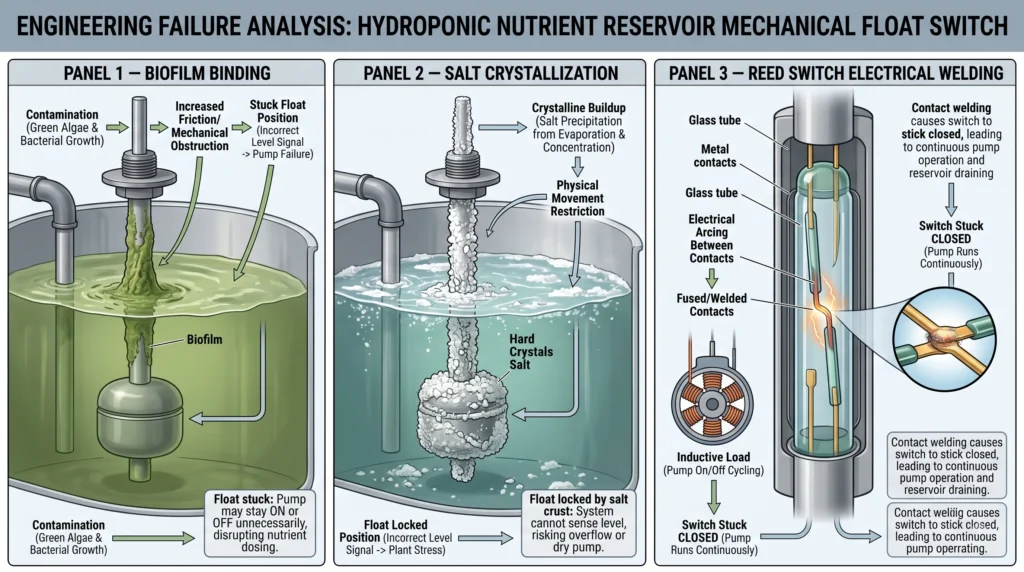
Biofilm accumulation is the primary catalyst for mechanical failure. Bacteria and organic compounds adhere to the microscopic abrasions on the plastic stem caused by the continuous sliding of the float. This biological layer alters the external dimensions of the stem and increases the coefficient of friction.
Salt crystallization accelerates this binding effect. Hydroponic nutrient solutions contain high concentrations of calcium (Ca2+), magnesium (Mg2+), and sulfate (SO42-) ions. As the water level naturally fluctuates due to evaporation and pump cycling, a thin film of solution is left on the exposed portion of the stem. Evaporation leaves behind rigid crystalline structures. Once the static friction force caused by these salt crystals and biofilms exceeds the buoyant force of the float, the switch becomes physically stuck. If the switch sticks in the “ON” position as water recedes, the system will not trigger an auto top-off, leading to pump cavitation. You can integrate diagnostic checks for this by referencing our hydroponic troubleshooting guide.
Electrical degradation represents the second failure mode. Reed switches are highly susceptible to micro-welding when driving inductive loads directly. If a float switch is wired directly to a water pump without an intermediate relay, the sudden collapse of the pump’s magnetic field upon shutdown creates a massive voltage spike. This spike arcs across the tiny gap in the reed switch, fusing the metal contacts together. The switch will remain permanently closed, resulting in an endless pumping cycle and eventual reservoir overflow.
The Physics and Mechanics of Optical Water Level Sensors
Optical sensors rely on the principles of infrared light refraction to detect the presence or absence of a liquid boundary. They contain absolutely no moving parts, rendering them immune to physical binding.
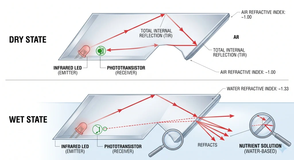
Optical water level sensors offer a solid-state alternative to mechanical switches. The architecture consists of an infrared (IR) light-emitting diode (LED) and an adjacent phototransistor, both housed behind a translucent polysulfone or glass prism. The operation relies on the distinct differences in the refractive indices of air versus water.
When the prism is exposed to air, the refractive index at the boundary is extremely low (air has a refractive index of approximately 1.00). The infrared light emitted by the LED strikes the inner surface of the prism and reflects internally, bouncing directly into the phototransistor. The receiving circuit registers this high-intensity light signal and translates it into a specific voltage output indicating a “dry” state.
When the nutrient solution rises and engulfs the prism, the optical dynamics shift entirely. Water has a refractive index of approximately 1.33. This physical parameter matches the refractive index of the prism material much more closely than air does. Instead of reflecting internally, the majority of the infrared light refracts outward, escaping into the liquid. The phototransistor experiences a severe drop in received light intensity. The internal circuitry processes this drop in photon reception and switches the output state to “wet”.
Failure Modes of Optical Systems
Optical sensors eliminate the threat of mechanical friction and salt-induced binding, but they introduce unique vulnerabilities tied to their optical requirements. To function correctly, the surface of the prism must remain capable of transmitting light.
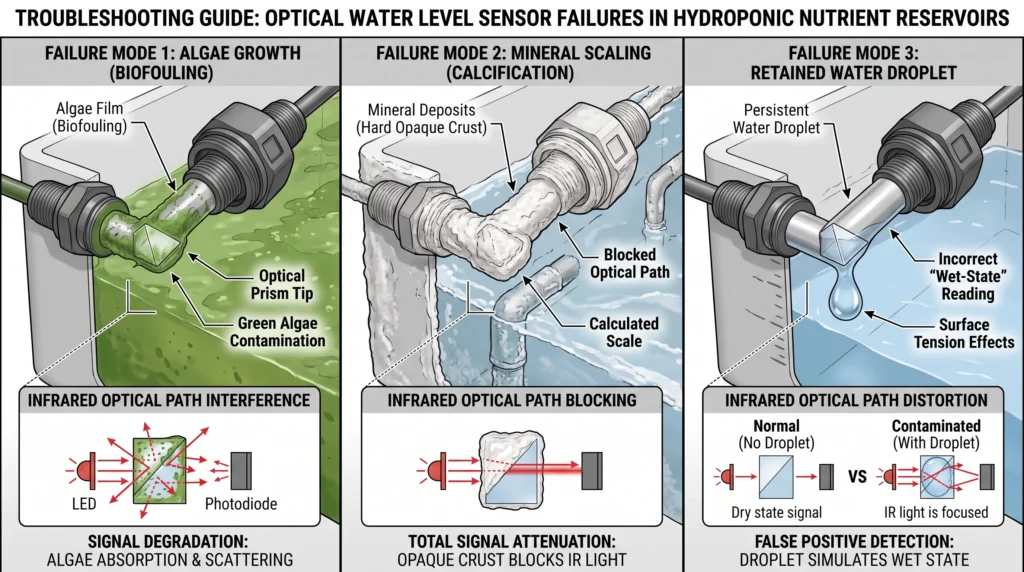
Algae proliferation is the leading cause of optical sensor malfunction in hydroponic environments. If light penetrates the sump tank, algal spores will colonize the submerged surfaces, including the sensor prism. A thick layer of dense green algae covering the prism will block the infrared light from escaping into the water. Even when submerged, the light reflects off the inner surface of the algal mat and bounces back to the phototransistor. The sensor registers a false “dry” state, potentially triggering an endless flow from an auto top-off valve. Preventing light leaks is essential for stable optical sensor performance; strategies for tank management can be found in our DIY hydroponic systems guide.
Severe mineral scaling causes identical optical interference. If calcium carbonate precipitates out of the solution and forms an opaque white shell over the prism, the light reflection dynamics revert to the “dry” state regardless of the actual water level.
Liquid droplet retention can trigger false “wet” states. If the water level drops rapidly but a large droplet of nutrient solution clings to the tip of the prism, the light will continue to refract outward through the droplet. To mitigate this, engineers must mount optical sensors perfectly horizontal or pointing straight down, utilizing gravity to shed residual droplets quickly.

- The CQRobot non-contact liquid level sensor realizes non-contact detection of the liquid level in a closed container. It…
- The principle is to use the inductive capacitance of water to detect whether there is liquid. When there is no liquid cl…
- The changed capacitance signal is then input to the control IC for signal conversion, which converts the changed capacit…
- Why it’s necessary: Solid-state infrared detection eliminates the mechanical binding failures caused by salt crystallization in heavy nutrient mixes.
- Key Spec: 12-24V DC operating voltage with built-in reverse polarity protection and a single-pole, double-throw (SPDT) relay output.
Sump Tank Drawdown Calculations and Sensor Placement
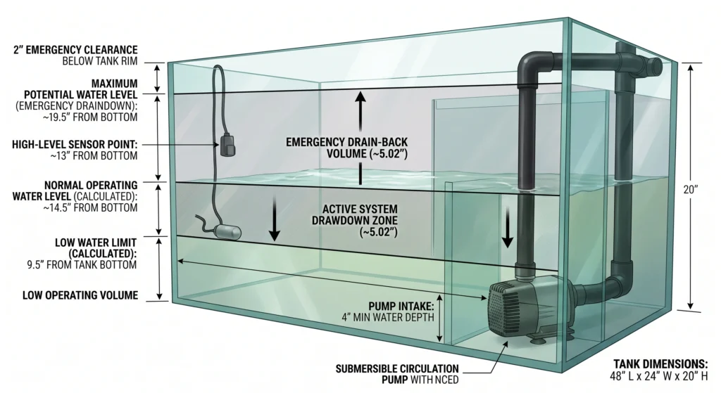
Correct sensor elevation prevents pump cavitation during active drawdown cycles and ensures adequate emergency overflow capacity when the entire system drains back into the sump during a power outage.
Sensor placement requires precise mathematical modeling of the system’s hydraulic volume. The sump tank must be sized to accommodate the active operating volume of the plumbing and grow beds, while retaining enough overhead space for emergency drain-back.
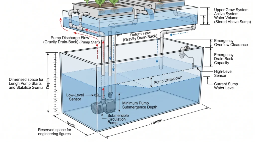
To calculate the exact placement of your low-level and high-level sensors, begin by quantifying the volume per inch of water height in the sump tank. For a standard rectangular reservoir, the formula is:
Assume a commercial sump tank measuring 48 inches long and 24 inches wide. The base area is 1,152 square inches. Dividing 1,152 by 231 reveals that every vertical inch of water in this specific tank equates to 4.98 gallons.
Next, calculate the total active system volume. This is the amount of water held inside the PVC plumbing lines, the grow trays, and the filtration manifolds while the main pump is running. If your calculations show that the system holds 25 gallons of water in the upper canopy during operation, the sump level will drop exactly 5.02 inches (25 gallons / 4.98 gallons per inch) the moment the pump engages and fills the upper system.
The low-level sensor must be placed to account for this drawdown. If the pump requires a minimum of 4 inches of water depth to prevent vortexing and cavitation (sucking air into the impeller), the absolute minimum static water level before the pump turns on must be 9.02 inches (4 inches for pump clearance + 5.02 inches for active drawdown). The low-level float switch or optical sensor should be permanently mounted exactly at the 9.5-inch mark to provide a safety margin. Detailed pump flow dynamics and head height calculations are mapped out in our hydroponic pump sizing guide.
The high-level sensor controls the maximum fill line. When the system shuts down, all 25 gallons of active water will drain backward through the plumbing into the sump, raising the water level by 5.02 inches. The high-level sensor must be mounted at an elevation that allows for this 5.02-inch rise without breaching the top rim of the sump tank. If the sump is 20 inches tall, the high-level sensor should not exceed an elevation of 13 inches from the bottom (20 inches total capacity – 5.02 inches drain-back – 2 inches emergency clearance = 12.98 inches). Mapping out these volumes ensures precise dosing metrics, which you can format using our hydroponic nutrient calculator.
Mitigating Environmental Variables: Turbulence and Stilling Wells
Surface agitation, return line splashing, and pump vibration create rapid oscillations in water level reading, leading to relay chatter and premature hardware failure.
Hydroponic sump tanks are violent hydraulic environments. Water cascades back from the grow trays, introducing massive surface turbulence. The main circulation pump generates high-frequency vibrations that travel through the tank walls. This turbulent environment degrades sensor accuracy.
If a float switch or optical sensor is mounted directly on the exposed wall of a turbulent sump, the rapid waves will cause the sensor state to flip back and forth between “wet” and “dry” multiple times per second. In electrical engineering, this rapid switching is known as contact bounce or relay chatter. When an auto top-off valve or pump relay chatters, the electromechanical contacts slam together repeatedly, causing massive heat generation, arcing, and eventual catastrophic failure of the automation controller. Evaluating relay durability is covered extensively in our breakdown of the best hydroponic controllers under $200.
To isolate sensors from wave action, engineers employ stilling wells. A stilling well is a physical barrier that surrounds the sensor, buffering it from surface turbulence while allowing the internal water level to slowly equalize with the tank volume.
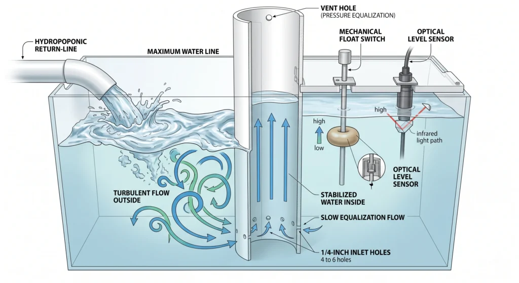
A DIY stilling well is easily constructed from a section of 2-inch or 3-inch PVC pipe. The pipe is capped at the bottom, and a few small 1/4-inch holes are drilled near the base. The PVC pipe is mounted vertically inside the sump tank, extending above the maximum water line. The water level sensors are suspended inside the pipe. Because the inlet holes are small, the rapid waves and splashing outside the pipe cannot penetrate the barrier fast enough to cause sudden internal level changes. The water inside the stilling well rises and falls smoothly, providing a completely clean signal for the automation relays.
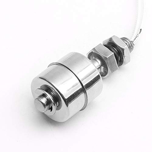
- ★This is a Mini stainless steel float switch,contains no mercury.
- ★This float switch is a device used to sense the level of liquid within a tank,the switch may activate a pump,an indicat…
- ★This Mini float switch is a simple structure,easy installation liquid level controller.It does not have a complex circu…
- Why it’s necessary: Industrial-grade stainless steel resists the corrosive effects of concentrated acidic pH adjusters and heavy fertilizer salts much better than standard ABS plastic switches.
- Key Spec: 304 Stainless steel body, rated for temperatures up to 120°C with a maximum switching current of 0.5A.
Electrical Integration: Circuits, Relays, and Fail-Safes
Sensors dictate the logic, but relays execute the physical labor. Proper circuit design isolates the delicate sensor electronics from the high-voltage demands of submersible pumps.
A standard optical sensor or mechanical float switch is designed strictly for low-voltage signal transmission. Typical operating voltages range from 5V to 24V DC, with a maximum current capacity of mere milliamperes (mA). Wiring a 120V AC water pump directly through a float switch will instantly melt the internal wiring and destroy the unit.
Safe integration requires a relay circuit. A relay is an electromagnetically operated switch. The low-voltage circuit containing the water level sensor connects to the relay’s electromagnetic coil. The high-voltage circuit containing the wall outlet and the water pump connects to the relay’s heavy-duty contact terminals.
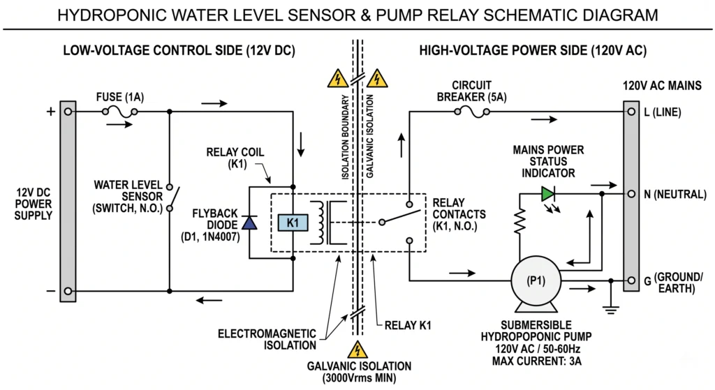
When the water level drops, the sensor closes the low-voltage circuit. The 12V DC current flows through the relay coil, generating a magnetic field. This magnetic field physically pulls the high-voltage contacts together, sending 120V AC power to the pump. The delicate sensor never interacts with the dangerous alternating current. Learning how to properly map low-voltage and high-voltage zones is explained in our guide on smart plugs and timers for hydroponics.
Protecting the sensor from the relay coil requires a specific electronic component known as a flyback diode. When the sensor opens the circuit to shut off the pump, the magnetic field in the relay coil collapses instantly. This collapse generates a sudden, high-voltage reverse current spike. Without a flyback diode wired in parallel across the relay coil to safely dissipate this energy, the voltage spike will travel backward into the optical sensor’s microchip, destroying the logic board.

- 4 Mode and Auto/Manual Switch:Water Suply,Drain,Lack Water Stop,Joint Mode.The controller also comes with manual and aut…
- Automatic Water Level Management: Monitors and controls water levels automatically, preventing overflow and dry running.
- Reliable Detector Sensor Technology: Equipped with high-quality detector sensors for accurate water level detection and …
- Why it’s necessary: A dedicated logic controller bridges the gap between low-voltage sensors and high-voltage pumps, providing safe, pre-wired relay integration without requiring custom breadboard soldering.
- Key Spec: Dual-sensor input logic (high/low bounds) with built-in debounce delay to prevent rapid relay chatter from minor surface ripples.
Engineering Redundancy: Two-Tier Fail-Safe Layouts
Relying on a single sensor technology introduces a single point of failure. Combining optical accuracy with mechanical durability guarantees operational continuity under extreme failure conditions.
Elite hydroponic automation demands redundancy. Given the high stakes of a flooded indoor grow room or a dehydrated root zone resulting in widespread crop death, commercial engineers never trust a single switch. A hybrid approach utilizing both optical and mechanical sensors offers the highest tier of system resilience. Understanding the financial implications of preventing these specific failure cascades is covered in our analysis of hydroponic system upgrades ROI.
A two-tier, hybrid automation layout assigns distinct roles to each sensor type based on their specific strengths.
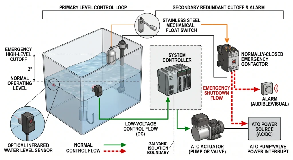
The primary control circuit is governed by the optical sensor. Optical sensors provide extreme precision, often triggering within a millimeter of fluid change. This makes them perfect for executing daily Auto Top-Off (ATO) operations, dosing fresh water in tiny, exact increments as evaporation occurs. This precision keeps the fertilizer concentration perfectly stable, avoiding the sharp electrical conductivity spikes analyzed in our hydroponic pH and EC mastery guide.
The emergency fail-safe circuit is governed by a stainless steel mechanical float switch. This mechanical switch is mounted exactly two inches higher than the optical sensor’s maximum trigger point. Under normal operating conditions, the water level never touches the float switch. It sits dry, waiting in standby mode.
If an electrical surge destroys the optical sensor’s microchip, or if dense algae growth tricks the optical eye into reading “dry”, the ATO pump will run continuously, flooding the tank. As the water rises past the failed optical sensor, it engages the mechanical float switch. This switch is wired directly into a normally closed (NC) master power contactor. The moment the float lifts, it breaks the power circuit to the entire ATO system, immediately stopping the rogue pump and firing an audible alarm. The mechanical simplicity of the float switch makes it the perfect physical override for a failed digital system.

- MT Duetto is an upgraded version features the external controller with a physical buttons, which supports one-touch paus…
- Compact size with integrated 1mm high-precision dual optical sensors. With a footprint of only 0.8 inches, it occupies m…
- Featuring a dual anti-overflow mechanism, this product incorporates an advanced anti-overflow sensor and a sophisticated…
- Why it’s necessary: A complete ATO kit provides the exact solenoid valves and mounting brackets required to automate reservoir filling directly from a reverse osmosis water line.
- Key Spec: Included dual-float redundancy; primary float controls the active fill logic while the upper float provides a hard physical emergency cutoff.
Diagnostic Testing and Maintenance Protocols
Routine electrical continuity checks and chemical descaling separate proactive system management from reactive disaster recovery.
Sensors subjected to heavily fertilized water require continuous validation. Implementing a rigid maintenance protocol ensures that components are replaced prior to catastrophic failure.
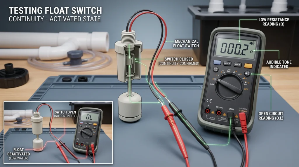
To test a mechanical float switch, disconnect it entirely from the control board. Set a digital multimeter to the continuity testing mode (the setting that beeps when a circuit is complete). Attach the two multimeter probes to the two output wires of the float switch. Manually slide the float up and down the stem. You must hear a sharp, instant beep the moment the float reaches the top, and total silence the moment it falls. If the multimeter registers high resistance (a fluctuating ohm reading instead of a solid zero) when closed, the internal reed switch contacts are corroded and the unit must be discarded.
Optical sensors require active voltage testing. Supply the required input voltage (e.g., 5V DC) to the power and ground wires. Connect the multimeter’s red probe to the sensor’s signal wire and the black probe to the ground wire. When the prism is dry, the signal wire should output a steady logic voltage (typically close to 5V or 0V, depending on the specific model’s NPN or PNP transistor configuration). Dip the prism into a cup of water. The voltage must shift instantly and cleanly to the opposite state. Sluggish voltage changes indicate internal transistor degradation or microscopic scratches on the prism interfering with refraction.
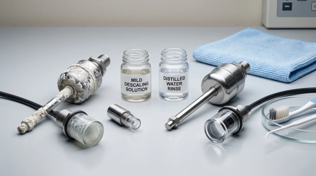
Physical cleaning dictates chemical precision. Mechanical scraping destroys sensor surfaces. Using a wire brush on a float switch stem creates micro-gouges that accelerate future salt accumulation. Scrubbing an optical prism with an abrasive pad permanently alters the refractive index of the plastic, ruining the sensor’s calibration.
Instead, utilize a mild acidic soak to dissolve calcium carbonate precipitation. Submerge the sensor tips in a 5% citric acid solution or distilled white vinegar for 45 minutes. The low pH environment safely dissolves the mineral bonds without degrading the polysulfone plastic or stainless steel housings. Rinse thoroughly with distilled water before reinstalling the hardware into the sump tank. Maintaining highly oxygenated, properly flowing water helps reduce the anaerobic conditions that accelerate biofilm growth, a principle similarly applied in hydroponic root rot prevention.
Heat also accelerates mineral scaling. Pumps running hot in a small sump tank increase the rate of water evaporation and localized salt precipitation directly onto nearby sensor brackets. By effectively managing thermal loads, as outlined in our passive hydroponic cooling guide, growers can extend the interval between required acid soaking procedures.
Frequently Asked Questions
How often should hydroponic water level sensors be replaced?
Preventative maintenance dictates replacing standard plastic float switches every 12 to 18 months, as continuous exposure to nutrient salts degrades the moving parts. High-quality optical sensors and 304 stainless steel float switches can operate reliably for 3 to 5 years, provided they undergo regular acid soaking to remove mineral scaling.
Can optical sensors detect nutrient solution levels in opaque tanks?
Yes. Optical sensors function by directly contacting the liquid. The internal infrared light refraction occurs at the exact boundary where the sensor prism touches the water. The opacity of the tank walls or the color of the nutrient solution itself does not interfere with the refractive physics of the prism.
What causes a mechanical float switch to fail in the ON position?
A mechanical float switch becomes stuck in the closed (ON) position due to either physical binding or electrical micro-welding. Calcium carbonate scaling or thick bacterial biofilm on the central stem creates physical friction, preventing the float from dropping. Electrically, running an inductive load like a water pump directly through the switch causes high-voltage arcing that permanently fuses the internal metallic reed contacts together.
How do you wire a float switch to a hydroponic pump relay?
The float switch must be wired to the low-voltage control side (the coil) of a solid-state or electromechanical relay. A 12V DC power supply routes positive current to the float switch, then out to the relay coil, and back to the ground. The high-voltage 120V AC wall power is wired independently through the heavy-duty contact terminals of the relay directly to the water pump.
Are stainless steel float switches safe for hydroponic nutrient solutions?
Yes. Type 304 and 316 stainless steel alloys are highly resistant to the corrosive effects of standard hydroponic fertilizers, which consist primarily of nitrate and sulfate salts. However, concentrated exposure to phosphoric acid (pH Down) or hypochlorous acid (sterilizers) over long durations can cause pitting. Stainless steel switches must be mounted securely to prevent galvanic corrosion from stray electrical currents in the water.
Can I use an optical water level sensor with a Raspberry Pi controller?
Yes. Most standard optical liquid level sensors operate natively on 5V DC logic, making them directly compatible with the GPIO (General Purpose Input/Output) pins on a Raspberry Pi or Arduino microcontroller. Ensure the sensor specifies a digital logic output rather than an analog varying voltage, and verify that the current draw of the sensor’s IR LED does not exceed the maximum amperage limits of the logic board’s power rail.
Sump Tank Automation Mastery
Executing flawless hydroponic automation requires balancing the raw physics of fluid dynamics with precise electrical control circuits. Understanding the exact mechanical friction limitations of float switches versus the light refraction vulnerabilities of optical sensors empowers growers to design resilient, fail-safe architecture. Sump tanks represent the beating heart of a recirculating system, and implementing a rigorous multi-tier sensor array guarantees that your reservoir remains perfectly balanced under any operational stress load. To explore the broader landscape of analytical probes and digital integration, review our comprehensive hydroponic sensors guide.

Continue Your Learning Journey