Advanced Grow Room Engineering: Ventilation & Design

Table of Contents
- The Physics of Grow Room Airflow and Static Pressure Loss
- AC Infinity Cloudline Series: Technical Performance Data
- Hydraulic System Design and Component Specification
- Sensor Integration and Automated Control Frameworks
- Installation and Commissioning Procedures
- Operation, Maintenance, and Calibration Protocols
- Troubleshooting Faults and Anomaly Resolution
- Safety Systems and Risk Mitigation
- Economic Analysis and Strategic Business Planning
- Frequently Asked Questions
- Elevating Your Grow Room Infrastructure
Disclosure: MistCulture summarizes verified product specs, engineering data, and community feedback. We may earn an affiliate commission if you purchase through our links. Regulations vary by location; this content is for educational purposes only.
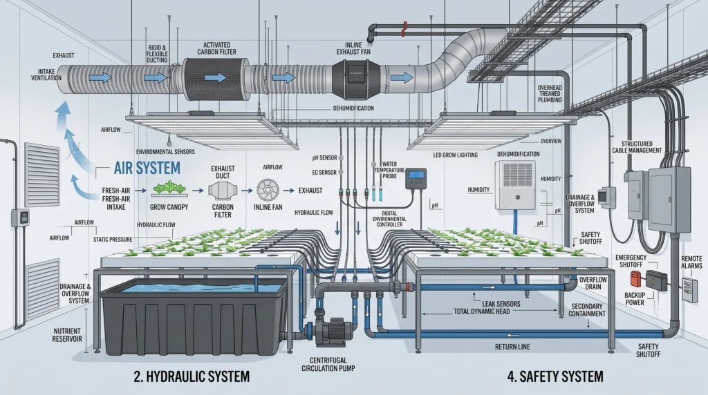
Controlled environment agriculture requires absolute precision across both aerodynamic and hydraulic systems. Plant metabolism relies entirely on the successful regulation of temperature, humidity, carbon dioxide enrichment, and nutrient delivery. When any single variable drifts out of the optimal range, crops suffer immediate physical stress, leading to diminished yields and compromised quality. Designing an efficient grow room means treating air and water management as interacting mechanical systems rather than isolated components.
From calculating static pressure losses in complex ducting networks to sizing centrifugal pumps for nutrient recirculation, every engineering decision dictates the long-term viability of your operation. We will examine the exact math required to size your environmental controls, review baseline data from the industry-standard AC Infinity Cloudline series, and outline the rigorous operational protocols necessary to keep your hydroponic infrastructure running at peak efficiency.
The Physics of Grow Room Airflow and Static Pressure Loss
Air circulation dynamics dictate the uniformity of your internal environment. Laminar airflow provides consistent baseline conditions, while turbulent airflow creates necessary mixing to replenish CO2 at the leaf surface, though excessive turbulence can inflict physical damage on delicate plant tissues.
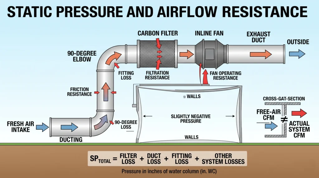
Ventilation is the backbone of grow room engineering. Proper exhaust mechanics remove accumulated heat and transpirational humidity while pulling fresh, CO2-rich air into the plant canopy. Many operators mistakenly select inline fans based purely on the manufacturer’s free-air Cubic Feet per Minute (CFM) rating. This approach ignores the reality of fluid dynamics. Every component attached to your ventilation circuit restricts airflow, creating static pressure resistance.
To engineer an efficient air exchange system, you must calculate the total resistance your fan will face. The industry standard measures this resistance in inches of water column (WC). Each component adds a specific drag factor:
- Activated Carbon Filter: 0.5 to 1.0 inches WC
- Flexible Vinyl Ducting (6-inch diameter): 0.15 to 0.25 inches WC per 10 feet
- 90-Degree Elbows/Bends: 0.15 to 0.30 inches WC per bend
- Inline Fan Housing: 0.1 to 0.5 inches WC depending on internal geometry and impeller speed
Consider a standard 4×4 grow tent connected to a comprehensive carbon scrubbing system. The physical setup requires an exhaust fan, a heavy-duty carbon filter, 8 feet of ducting, and two sharp 90-degree bends to route the air outside. The total static pressure calculation looks like this: SP_total = SP_filter + SP_duct + SP_bends.
Plugging in the variables: 0.75 + (8 / 10 * 0.20) + (2 * 0.25) = 0.75 + 0.16 + 0.50 = 1.41 inches WC.
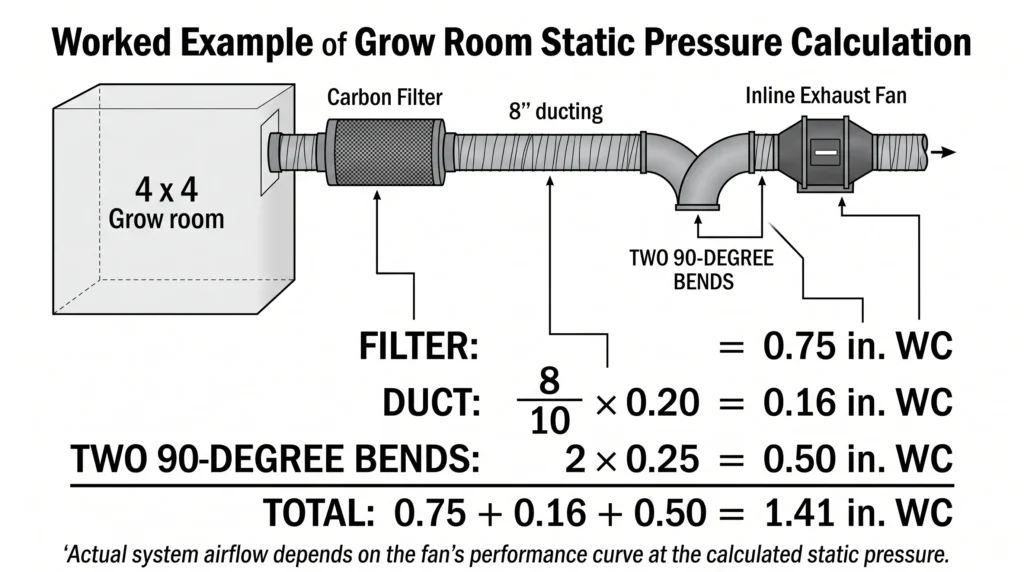
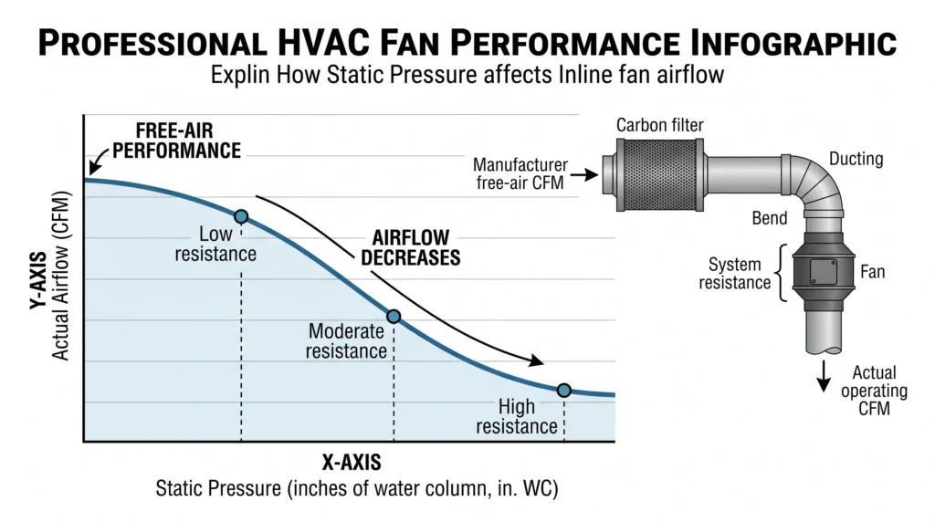
When pushed against 1.5 inches of water column resistance, a standard fan rated for 400 CFM in free air will experience a massive performance drop, delivering only 200 to 250 actual CFM. Failing to account for this drop leaves your environment prone to heat spikes and humidity accumulation. To navigate these physical constraints successfully, you need to over-engineer your fan capacity and select equipment built with high-static-pressure impellers. Check our grow tent buying guide to see how structural port placements affect your ducting layouts.
AC Infinity Cloudline Series: Technical Performance Data
The AC Infinity Cloudline series utilizes electronically commutated (EC) motors and pulse-width modulation (PWM) control to deliver high static pressure performance at incredibly low acoustic profiles.
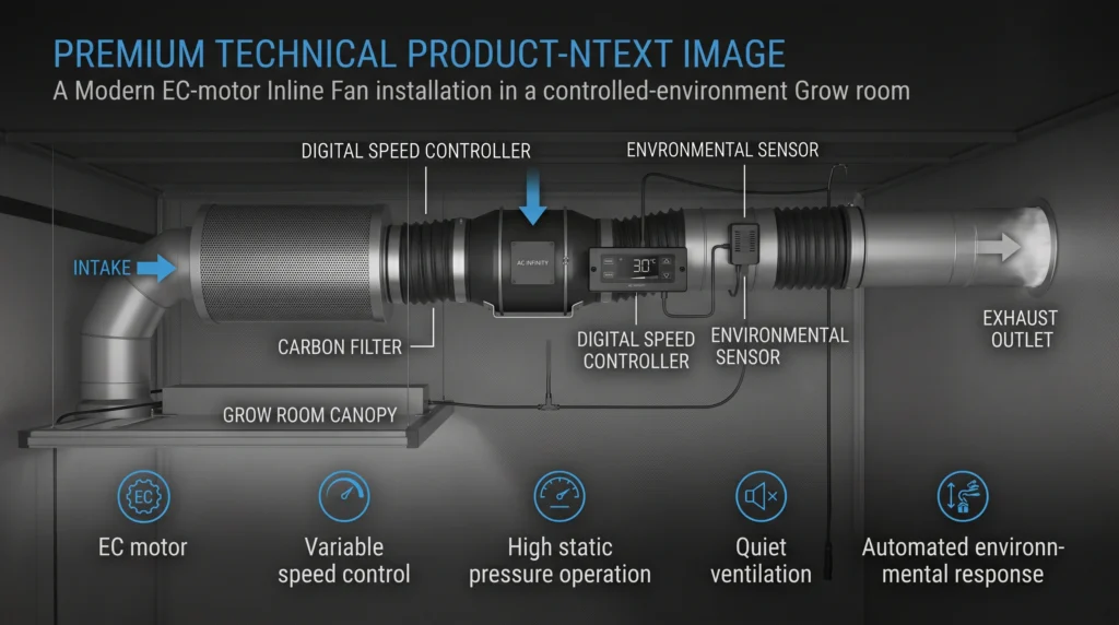
In controlled environment agriculture, standard AC motors are rapidly becoming obsolete. They generate excessive heat, consume high amounts of wattage, and produce a loud electrical hum when restricted by speed controllers. AC Infinity engineered the Cloudline series specifically to combat these issues, utilizing EC motors that maintain torque even when dialed down to minimal speeds. Our performance tests focus on how these fans handle the resistance of standard grow room attachments.
The Cloudline T4 model is an ultra-compact 4-inch fan pushing 102 CFM at free air. It is uniquely suited for specialized curing tents or vegetative cloning chambers. At lower PWM speeds, it operates at a nearly imperceptible 22 dBA. The Cloudline T6 is the undisputed industry standard for mid-sized setups, pushing 351 CFM. When paired with standard carbon filters, it retains enough pulling power to exchange the air in a heavy-canopy 4×4 tent multiple times per minute. For operators facing extreme static pressure challenges—such as long, winding duct runs or heavily packed carbon scrubbers—the Cloudline S6 acts as the high-static-pressure variant. Rated at 440 CFM, the S6 features an aggressive impeller pitch designed to bite into heavy air, sacrificing a slight amount of acoustic stealth for maximum pulling force.

- Designed to ventilate hydroponic grow rooms, transfer heating/cooling, cool AV closets, and exhaust odors.
- Dynamic temperature and humidity programming, with timers, grow cycles, scheduling, minimum speed.
- Remotely connect to our WiFi app to access advance programs, view climate data, and set automation.

- Designed for ventilation applications including HVAC, dryer, grow rooms and tents.
- Four-layer design makes it more durable and resistant to leaks, tears, and cuts.
- Steel-wire spiral structure is flexible and easy-to-install in hard to reach places.

- Reusable carbon filter features a patented design that eliminates the need to replace entire filters.
- Includes 1+ refill to match the filtration capacity of two standard 6” carbon filters while costing less.
- Removable twist-off flanges support easy, tool-free refilling using the included funnel and scoop.
Hydraulic System Design and Component Specification
Engineering the water delivery system dictates the long-term reliability of a hydroponic farm. System layout requires careful attention to component positioning, flow path optimization, access for maintenance, and structural material compatibility.
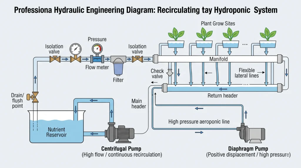
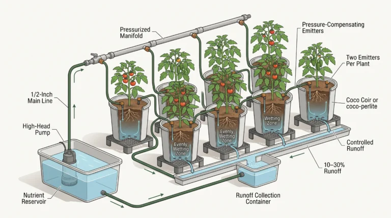
Moving air is only half the battle; moving water efficiently determines whether your crop receives the precise mineral profiles required for aggressive growth. The design process involves requirements analysis, conceptual drafting, physical prototyping, and rigorous pressure testing. You must select pumps sized accurately for both desired flow rates and total dynamic head pressure. For a deeper understanding of volume requirements, review our hydroponic pump sizing guide.
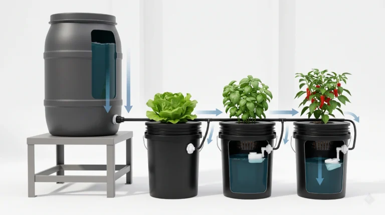
Centrifugal pumps handle the heavy lifting in recirculating systems like Deep Water Culture (DWC) or Nutrient Film Technique (NFT). They use a spinning impeller to generate velocity, transferring large volumes of fluid at relatively low pressures. Conversely, diaphragm pumps operate using positive displacement, making them ideal for high-pressure applications like aeroponic misting manifolds or precise nutrient dosing systems.
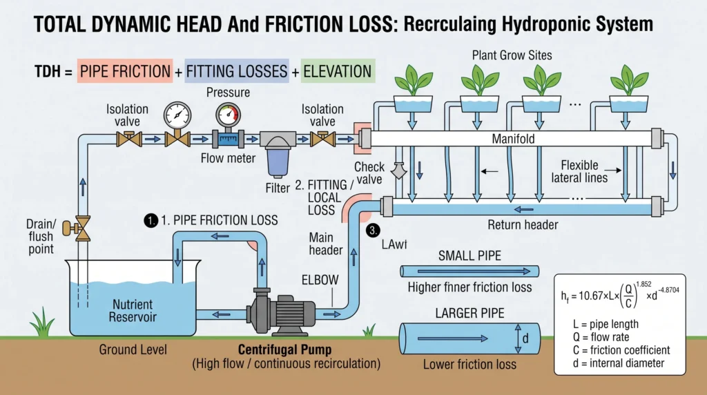
Sizing these components requires mathematical rigor. You must calculate total pressure drop, which includes pipe friction, fitting losses, and elevation changes. The formula for friction loss in straight pipes relies on internal roughness and fluid velocity. A common approach uses a variation of the Hazen-Williams equation, often simplified for standard PVC plumbing as h_f = 10.67 * L * (Q / C)^1.852 * d^-4.8704, where L is pipe length, Q is flow rate, C is the friction coefficient, and d is the internal diameter. Because biofilms and root debris eventually accumulate in pipes, engineers apply a safety factor of 1.5 to 2.0 times the calculated minimum value to account for unexpected restrictions and to guarantee overhead for future system expansion.
Material selection directly impacts chemical stability. The nutrient solution is a highly reactive blend of mineral salts and acids. Stainless steel provides superior durability for impellers and submerged shafts, but carries a higher upfront cost. Food-grade plastics like high-density polyethylene (HDPE) or unplasticized polyvinyl chloride (UPVC) offer excellent chemical resistance for plumbing lines. Avoid any brass or copper fittings, as nutrient acids rapidly strip copper ions into the water, causing heavy metal toxicity in your plants. Ensure you check every component against the parameters found in our hydroponic gear guide to verify material safety.
Sensor Integration and Automated Control Frameworks
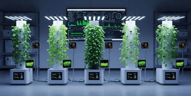
Control systems act as the central nervous system of your grow room. They monitor environmental drifts and execute physical responses. A programmable logic controller (PLC) offers industrial-grade reliability, while consumer-tier single-board computers provide high flexibility for custom tent setups.
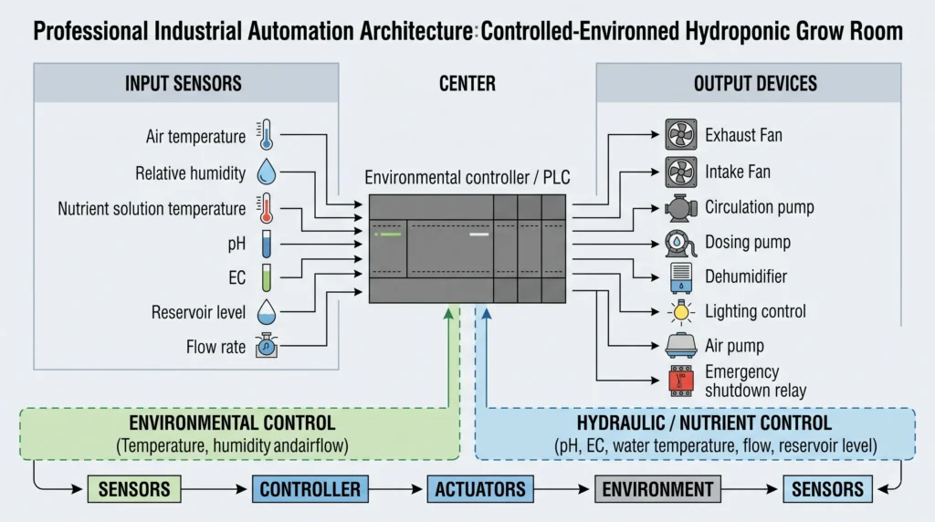
To maintain total system awareness, your sensor array must be responsive and highly accurate. Temperature probes utilized in the nutrient reservoir should guarantee an accuracy variance of no more than plus or minus 0.5 degrees Celsius. Hydraulic temperature directly dictates dissolved oxygen capacity; warmer water holds less oxygen, starving roots and encouraging anaerobic pathogen replication. We discuss managing thermal limits in our passive hydro cooling guide.
Electrical Conductivity (EC) and pH sensors require frequent calibration because they endure constant submersion in corrosive mineral baths. The glass bulb of a pH probe degrades over time, experiencing voltage drift that can trick an automated doser into dumping excess acid into the reservoir. Utilizing controllers with robust data logging capabilities allows you to plot sensor data over time. Observing a gradual, unnatural curve in pH readings often indicates a failing probe rather than a true chemical shift in the water. Compare the best options on the market by reading our breakdown of hydroponic controllers under $200.
Installation and Commissioning Procedures
Proper installation ensures system reliability from day one. You must test all components individually and holistically before introducing biological assets to the environment.
Rushing the commissioning phase guarantees catastrophic leaks and crop loss. Installation requires strict adherence to fluid dynamics principles. When routing flexible tubing or rigid PVC, eliminate sharp 90-degree elbows wherever possible, substituting them with sweeping 45-degree bends to reduce water hammer effects and friction loss. Secure all overhead lines with heavy-duty brackets to prevent sagging, as sags create air locks that choke flow rates.
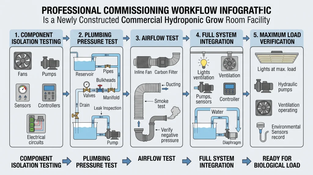
The formal commissioning checklist includes isolated component testing, full system integration, and maximum load verification.
- Component Isolation Testing: Run the exhaust fans independently at maximum speed. Check all ducting joints for negative pressure leaks using a smoke pencil. Fire the water pumps in isolated buckets to verify their amp draw matches the manufacturer’s rating.
- System Integration: Connect the pumps to the main manifold. Fill the reservoir with plain, reverse-osmosis water. Initiate flow and inspect every thread, bulkhead, and slip joint for micro-leaks. Let the system run fully pressurized for 48 hours.
- Maximum Load Verification: Turn on all intense grow lights, activate the hydraulic pumps, and set the ventilation to automatic. Observe the environmental response. The exhaust system must demonstrate the ability to pull temperatures down to the baseline target even while the lights radiate maximum thermal energy.
Startup procedures demand patience. Begin by running the completed system with pure water to verify perfectly balanced hydraulic distribution across all plant sites. Introduce base nutrients at half-strength for the first week of plant growth. Young root systems suffer severe osmotic shock if subjected to aggressive mineral concentrations immediately after transplanting. Gradually scale up to full vegetative strength over a two-week period, tracking the resulting growth rates closely. You can precisely map out this mineral escalation using our hydroponic nutrient calculator.
Operation, Maintenance, and Calibration Protocols
Regular, scheduled maintenance extends equipment life and halts cascading failures. Digital maintenance management tracks work orders and highlights predictive failure patterns.
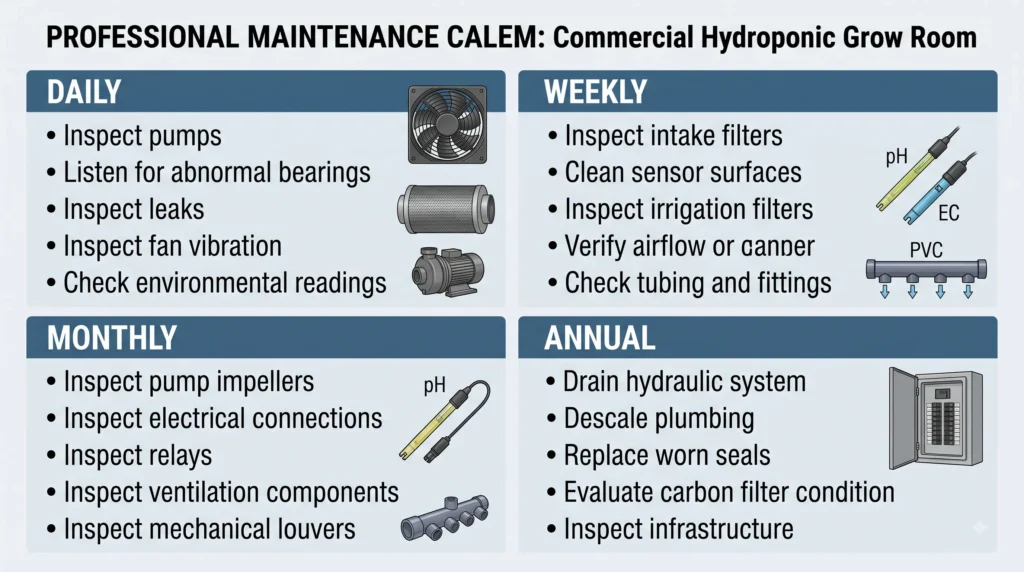
System operators must walk the floor daily, engaging in strict visual and auditory inspections. Listen for the high-pitched whine of a failing pump bearing. Look for salt crust accumulation around PVC joints, which points to microscopic pressure leaks. Verify that the fan blades spin without asymmetrical wobble.
Weekly maintenance targets filtration and sensor accuracy. Pre-filter elements on the intake ventilation lines catch heavy dust and pest ingress; wash or replace these weekly to prevent the inline fan from choking. In hydraulic systems running thick, organic-based nutrients, inline screen filters require weekly purging to prevent organic sludge from restricting emitter flow. Clean the glass bulbs of your pH sensors with a soft brush and soak them in a KCl storage solution to restore their sensitivity. We outline advanced calibration techniques in our hydroponic pH and EC mastery guide.
Monthly overhauls require partial system shutdowns. Isolate the main water pumps and inspect the impeller housings for tangled root mass. Check all electrical connections—especially high-draw lighting ballasts and pump relays—for signs of heat discoloration or oxidation. Lubricate mechanical louvers on the intake vents to ensure they snap shut smoothly when the exhaust fan powers down, sealing the room from external contaminants.
Annual maintenance serves as a total infrastructure reset. Drain the entire hydraulic loop. Flush the lines with a specialized descaling acid to dissolve calcium carbonate buildup inside the pipes. Replace worn silicone gaskets on your bulkheads. Evaluate the activated carbon in your exhaust filters; heavily saturated carbon beds add massive static pressure to your fans and fail to scrub volatile organic compounds effectively. Replace the carbon entirely to restore baseline airflow.
Troubleshooting Faults and Anomaly Resolution
Systematic troubleshooting minimizes downtime. Diagnostic procedures isolate faulty elements through parameter logging and environmental context.
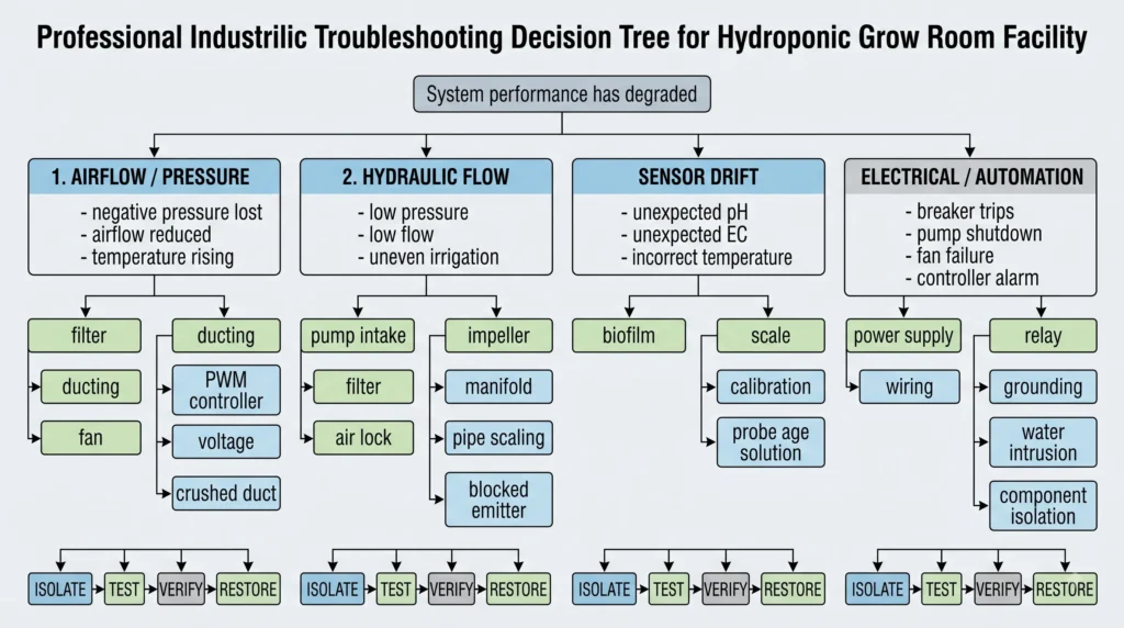
When a grow room fails, it usually does so through a chain reaction of small anomalies. Mastering root cause analysis means looking past the immediate symptom to find the mechanical origin. For extensive diagnostic flowcharts, reference our hydroponic troubleshooting guide.
Airflow and Pressure Anomalies:
If the grow tent loses negative pressure (the walls bow outward instead of sucking inward), the exhaust system is failing. Check the pre-filter on the carbon scrubber for heavy dust occlusion. Inspect the length of the ducting for tears or crushed sections. If the physical path is clear, the inline fan’s motor may be suffering from voltage drop, or the PWM controller might have drifted from its setpoints.
Hydraulic Flow Rate Degradation:
A drop in water pressure at the plant sites points to an obstruction or mechanical wear. Verify that the pump intake screen is clear of debris. Check the main manifold for air locks. If the physical lines are clear, inspect the pump impeller. Mineral scaling can bind the magnetic drive, slowing rotation and drastically cutting head pressure.
Environmental Sensor Drift:
When the automated controller dumps excess acid into the reservoir but the plants exhibit alkaline lockout symptoms, your sensor is lying to the system. Biofilm coats the sensor probes, insulating them from the actual fluid chemistry. Clean the probes thoroughly. If calibration solutions fail to reset the probe to a perfect 4.0 or 7.0 reading, the internal reference solution is exhausted, and the probe requires immediate replacement. Review the best probe maintenance strategies in our hydroponic sensors guide.
Electrical and Automation Faults:
Tripped breakers suggest a short circuit or an overloaded relay. Water and electricity exist in dangerous proximity in hydroponics. Inspect all drip loops on your power cables. Ensure that water cannot travel down a cord into an outlet. If a specific pump or fan repeatedly triggers a fault, isolate the component and test it on an independent circuit with a multimeter to check for internal casing shorts.
Safety Systems and Risk Mitigation
Protecting your biological assets and physical equipment requires overlapping layers of redundancy. Single points of failure destroy crops. An emergency shutdown framework protects the facility when automated systems act erratically.
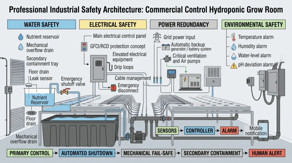
Implement physical fail-safes. Gravity-fed overflow drains must be installed in every reservoir and plant tray. If an electronic float switch sticks in the “open” position, the refill pump will run indefinitely. Without a mechanical overflow drain routed safely to a floor sink, the system will flood the facility, destroying electrical gear and causing catastrophic water damage.
Redundancy ensures survival during utility disruptions. Relying on grid power alone invites disaster during severe weather events. Backup generators or large-capacity battery banks must automatically kick on to power the air pumps and ventilation fans. Plant roots submerged in stagnant water deplete available dissolved oxygen in hours; maintaining air pump operation is non-negotiable.
Implement remote notification protocols. Status indicators and alarm triggers must push alerts to mobile devices. High-temperature spikes, water-floor-sensor trips, or rapid pH deviations require immediate human intervention. Digital controllers mapped to IoT networks execute these alert systems seamlessly. We explore these integrations heavily in our hydroponic IP and pest management guide.
Economic Analysis and Strategic Business Planning
Long-term sustainability requires balancing capital investment against operational savings and maximized yield outputs.
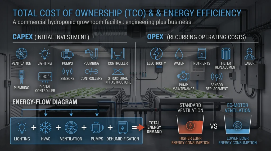
Scaling a hydroponic build from a hobby tent to a commercial facility requires rigorous financial modeling. You must calculate the Total Cost of Ownership (TCO), dividing expenses into Capital Expenditure (CapEx) and Operational Expenditure (OpEx). CapEx includes the initial purchase of AC Infinity fans, heavy-duty shelving, lighting arrays, and plumbing infrastructure. OpEx covers the ongoing costs of electricity, raw mineral salts, replacement carbon filters, and water consumption.
Energy consumption dominates the OpEx ledger. Lighting and HVAC (Heating, Ventilation, and Air Conditioning) draw massive wattage. Calculating the exact ROI on high-efficiency equipment justifies the initial premium price. Switching from standard AC exhaust fans to EC motor fans reduces ventilation energy consumption by up to 40%. Analyze your upgrade paths using the data mapped out in our hydroponic system upgrades ROI guide.
Yield correlation ties directly to environmental stability. By logging your atmospheric data against harvest weights, you identify the exact temperature and humidity bands that maximize your specific cultivar’s output. Resource efficiency analysis exposes wasted nutrients. Utilizing hydroponic water efficiency calculators helps operators dial in their transpiration rates, reducing the required volume of top-off water and lowering dehumidification energy costs.
Frequently Asked Questions
How does static pressure affect inline fan performance in a grow tent?
Static pressure is the physical resistance against airflow caused by ducting, filters, and bends. When a fan pushes against high static pressure, its actual CFM output drops significantly. High-static-pressure fans, like those utilizing EC motors and specialized stator blades, are engineered to maintain their rated airflow even when pulling through dense activated carbon beds.
What is the maximum acceptable temperature variance for hydroponic nutrient solutions?
Nutrient solutions should ideally remain between 65°F and 68°F (18°C – 20°C). If temperatures climb above 72°F (22°C), the water’s ability to hold dissolved oxygen plummets, opening the door for anaerobic pathogens like Pythium (root rot). Temperatures below 60°F (15°C) can shock the root system and lock out the absorption of heavier elements like phosphorus.
Why do my pH and EC sensors drift, and how often should I calibrate them?
Sensors drift due to the accumulation of mineral scale and organic biofilms on the glass measuring bulbs, which insulate the probe from the actual fluid chemistry. Probes should be visually inspected weekly, cleaned gently with a soft brush, and recalibrated against standardized 4.0 and 7.0 buffer solutions at least once a month to guarantee dosing accuracy.
How do I size the exhaust fan for a sealed grow room?
Calculate the total cubic volume of the room (Length x Width x Height). For active air exchange, you want a fan capable of clearing that entire volume once every minute. Take that baseline CFM number and multiply it by a safety factor of 1.3 to 1.5 to account for the static pressure losses introduced by your carbon filters and ducting bends.
What is the difference between a centrifugal pump and a diaphragm pump in hydroponics?
Centrifugal pumps use a spinning impeller to move large volumes of water at low pressures, making them ideal for continuous recirculation in NFT or DWC systems. Diaphragm pumps use positive displacement to push small, exact volumes of water at very high pressures, making them necessary for precise nutrient dosing or high-pressure aeroponic misting manifolds.
How can I reduce the acoustic noise of my grow room ventilation?
To silence airflow, utilize insulated vinyl ducting instead of bare aluminum foil, which vibrates and amplifies sound. Keep ducting runs as straight and taut as possible to eliminate turbulent air pockets. Suspend your inline fans using bungee cords or rubber dampeners to prevent motor vibrations from transferring into the rigid structural poles of the grow tent.
Elevating Your Grow Room Infrastructure
Achieving absolute control over your growing environment is an ongoing process of monitoring, adjusting, and upgrading. Balancing the fluid dynamics of your nutrient delivery with the aerodynamic requirements of your exhaust system ensures that your plants never experience baseline stress. When the mechanics run flawlessly, the biology thrives.
If you are ready to start planning your specific operational layout and calculating exact mineral requirements for your scaled system, head over to our comprehensive Hydroponic Nutrient Calculator to formulate your next aggressive growth cycle.

Continue Your Learning Journey