Commercial Automated Nutrient Dosing Skid Setups for Small Farms

Table of Contents
- Dosing Skid Architecture and Manifold Design
- Fluid Dynamics and Injection Calculations
- Component Selection: Peristaltic vs. Diaphragm Pumps
- Sensor Integration and PLC Automation
- Installation and Commissioning Procedures
- Advanced Troubleshooting and Problem Resolution
- Performance Monitoring and Preventative Maintenance
- Safety Systems and Failsafe Engineering
- Economic Analysis and Scalability
- Frequently Asked Questions
- Conclusion
Disclosure: MistCulture summarizes verified product specs, engineering data, and community feedback. We may earn an affiliate commission if you purchase through our links. Regulations vary by location; this content is for educational purposes only.
Scaling a hydroponic farm from a garage hobbyist setup into a profitable 5,000-square-foot commercial operation forces a hard reality check. Mixing nutrients by hand stops being a minor weekend chore. It transforms into a massive labor sink that introduces dangerous inconsistencies into your crop cycle. Hand-dosing a 1,000-gallon reservoir leaves room for human error, pH swings, and crop loss. Commercial automated nutrient dosing skids eliminate these variables. They package peristaltic pumps, sensor arrays, distribution manifolds, and programmable logic controllers (PLCs) onto a single mountable frame.
This guide strips away the marketing jargon surrounding commercial fertigation systems. We break down exact sizing calculations, analyze pressure drop mechanics in dosing manifolds, and outline exact installation and troubleshooting procedures. By standardizing your nutrient delivery, you protect your crop yield and build a farm capable of scaling predictably.
Dosing Skid Architecture and Manifold Design
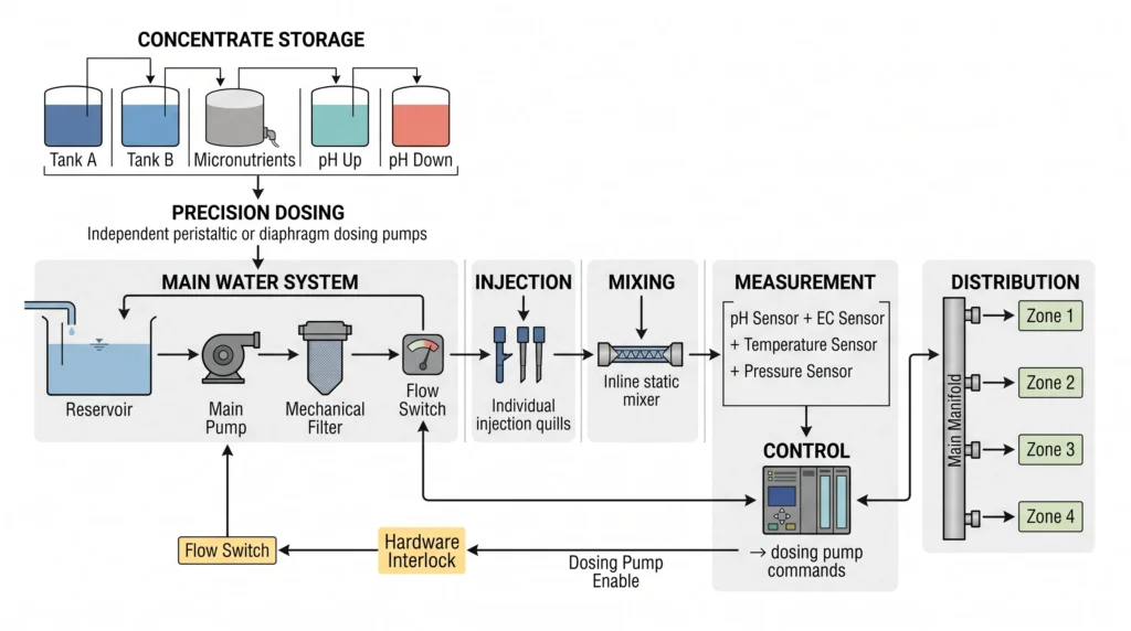
Automated dosing skids centralize the storage, measurement, and injection of nutrient concentrates into a main irrigation line. Designing this architecture correctly prevents chemical precipitation and ensures uniform nutrient delivery across multiple grow zones.
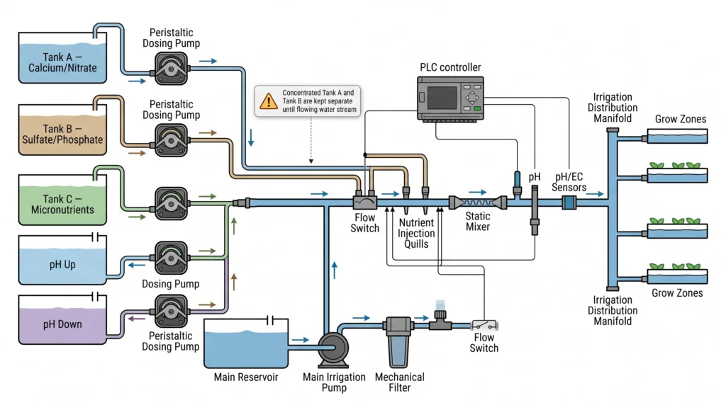
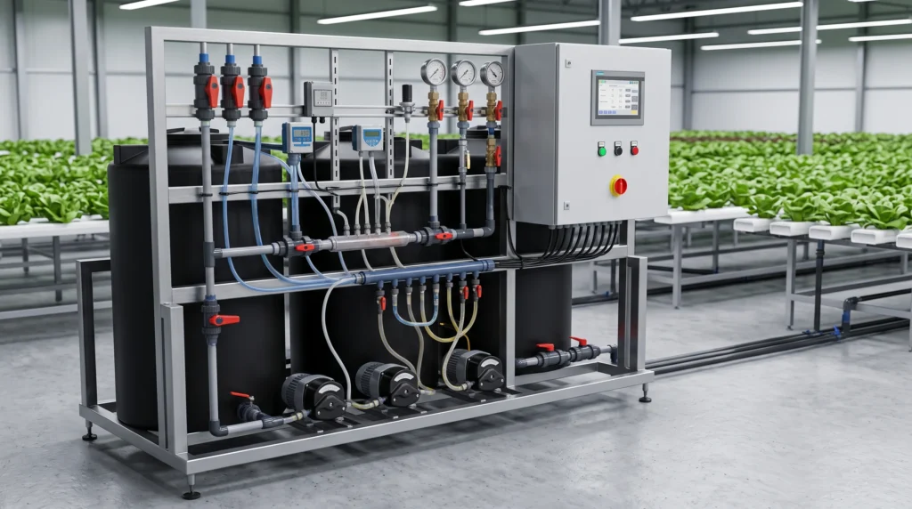
A standard commercial dosing skid integrates three to five concentrate tanks. You typically have Tank A for calcium nitrate, Tank B for magnesium sulfate and phosphates, Tank C for micronutrients, and separate reservoirs for pH UP and pH DOWN. Mixing concentrated Tank A and Tank B directly causes calcium sulfate (gypsum) to precipitate and fall out of solution. The skid architecture prevents this by injecting concentrates sequentially into a flowing mixing chamber or directly into the main irrigation line through an inline static mixer.
For a facility managing 1,000 to 5,000 square feet of canopy, a single dosing skid can serve multiple zones. The skid draws from the concentrate tanks using stepper-motor-driven dosing pumps. These pumps inject the liquid into a pressurized manifold. The manifold must be constructed from Schedule 80 PVC or 316 stainless steel to withstand constant exposure to corrosive salts and acids.
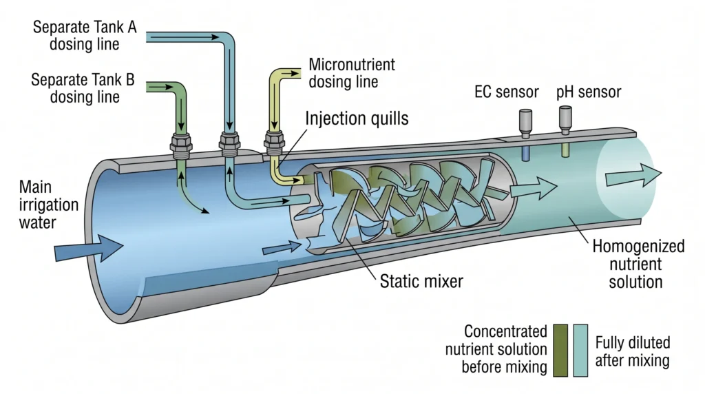
In an inline injection setup, the main irrigation pump pushes water through the manifold. The dosing pumps inject nutrients into this flow. The water then passes through a static mixer, a series of internal baffles that force the fluid to fold over itself, ensuring the nutrients are fully dissolved before reaching the monitoring sensors. If the sensors read a low electrical conductivity (EC), the PLC commands the pumps to inject more concentrate.
If you are planning the main irrigation lines that connect to this skid, refer to our hydroponic pump sizing guide to ensure you provide adequate flow velocity through the injection manifold. Low velocity leads to poor mixing and erratic sensor readings.
Fluid Dynamics and Injection Calculations
Precise dosing requires exact mathematical modeling of dilution ratios and flow rates. Failing to calculate the injection volume correctly leads to erratic pump cycling, overshoot, and dangerous nutrient lockout conditions.
To size your dosing pumps and concentrate tanks, you must calculate the required injection volume based on your main irrigation flow rate and target EC.
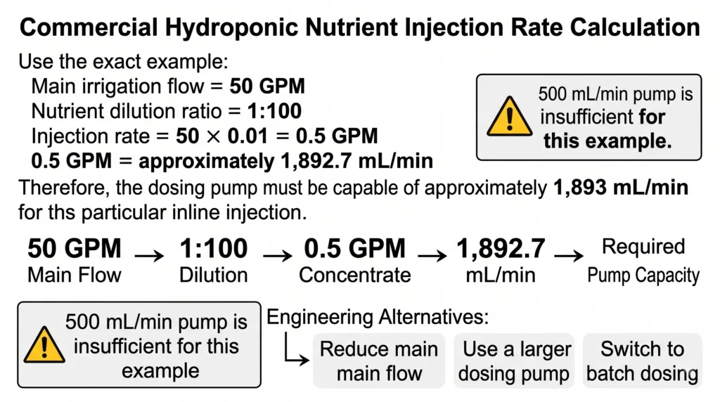
Assume your main irrigation pump moves water at 50 gallons per minute (GPM). You want to raise the EC from a baseline of 0.2 to 2.0 mS/cm. Your nutrient manufacturer specifies a dilution ratio of 1:100 (1 part concentrate to 100 parts water) to achieve an EC of 2.0.
First, determine the volume of water passing through the manifold per minute:
Main Flow = 50 GPM
Apply the dilution ratio to find the required injection rate for Tank A:
Injection Rate = Main Flow * (1 / 100)
Injection Rate = 50 * 0.01 = 0.5 GPM
Convert GPM to milliliters per minute (mL/min), as dosing pumps are rated in mL/min:
1 Gallon = 3785.41 mL
0.5 Gallons = 1892.7 mL
Your dosing pump for Tank A must be capable of delivering 1,892 mL/min. If your dosing pump maxes out at 500 mL/min, you cannot run this as an inline injection system at 50 GPM. You must either slow the main flow rate, buy larger dosing pumps, or switch to a batch-dosing reservoir setup where the skid fills a holding tank slowly over time.
For routine checks on how individual salts impact your total parts per million (PPM), you can input your base water profile into our hydroponic nutrient calculator.
Component Selection: Peristaltic vs. Diaphragm Pumps
Pump selection dictates the accuracy and maintenance schedule of your dosing skid. Peristaltic pumps offer superior precision for low-volume injection, while diaphragm pumps handle high-pressure lines and larger volumes.
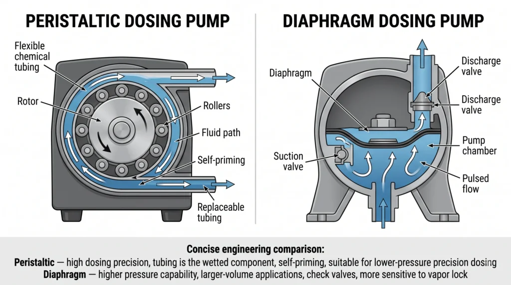
Dosing pumps are the mechanical heart of the skid. Most small commercial systems utilize peristaltic pumps. A peristaltic pump features a circular rotor with multiple rollers. As the rotor turns, the rollers compress a flexible chemical-resistant tube, forcing a precise volume of fluid forward. Because the fluid never touches the pump’s internal mechanics, corrosion is non-existent. You simply replace the tubing when it wears out.
Peristaltic pumps excel in accuracy down to the milliliter. They are self-priming and can run dry without catastrophic failure. Their limitation is pressure. Standard peristaltic tubing cannot inject into a main irrigation line running higher than 30 PSI. The backpressure will overcome the pinch of the rollers, causing fluid to slip backward.
If your irrigation manifold operates at 50 PSI or higher, you must use a solenoid-driven diaphragm dosing pump. A diaphragm pump uses an electromagnet to pulse a membrane back and forth. Intake and discharge check valves ensure the fluid only moves in one direction. Diaphragm pumps handle extreme pressures effortlessly. However, they are prone to vapor lock. If air gets into the suction line, the diaphragm compresses the air instead of liquid, stalling the injection process.
For smaller commercial farms, stepping the manifold pressure down with a pressure regulating valve (PRV) to accommodate peristaltic pumps is the most reliable approach.

- DIP1500 intelligent peristaltic pump, using high-precision long-life stepper motor, with a digital LED display to show t…
- Standard silicone tube S18#7.9mm IDx11.1mm OD(consumables,lifetime about 200H), easy to change tube, 3 rotors, speed ran…
- Support the functions of start-stop, reversing, speed regulation, calibration, reverse sucking back, etc. Precise contro…
- Why it’s necessary: This multi-channel dosing unit integrates seamlessly into smaller commercial skids, offering precise stepper-motor control and remote WiFi access for batch reservoir dosing.
- Key Spec: 4 independent channels, liquid flow rate of up to 50 mL/min per channel, mobile app integration.
Sensor Integration and PLC Automation
Industrial programmable logic controllers process analog signals from the manifold sensors and trigger the dosing pumps. Shielding these sensor cables from electromagnetic interference prevents false readings and chemical overdosing.
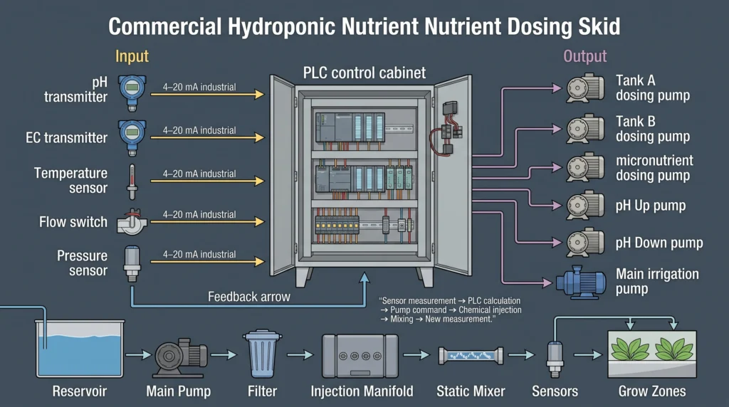
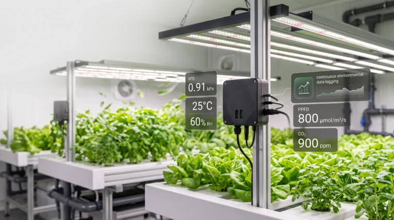
Your dosing skid is blind without high-grade sensors. Commercial skids use industrial transmitters to read pH and EC. Hobbyist probes output a raw, unamplified millivolt signal. This weak signal degrades quickly over distance and picks up electromagnetic interference (EMI) from nearby water pumps or ballast transformers.
Commercial transmitters convert the raw probe data into a robust 4-20mA analog loop signal. In a 4-20mA system, an EC reading of 0.0 mS/cm outputs exactly 4 milliamps of current. A reading of 5.0 mS/cm outputs exactly 20 milliamps. The PLC reads this current. Because it relies on current rather than voltage, the signal can travel hundreds of feet across the farm without degrading.
Proper placement of these sensors in the manifold is not negotiable. The probes must be installed downstream of the static mixer. They must remain fully submerged at all times. If installed at the highest point in a pipe, an air pocket will form around the probe tip, causing the PLC to read a sudden drop in EC. The PLC will react by commanding the dosing pumps to dump maximum nutrients into the line, burning the crop. Always install sensors in a U-trap or a vertical section of pipe with upward flow to guarantee submersion.
To understand exactly how temperature swings impact the conductivity readings of these probes, read our detailed hydroponic pH and EC mastery guide. You need to account for temperature compensation algorithms inside your PLC logic.
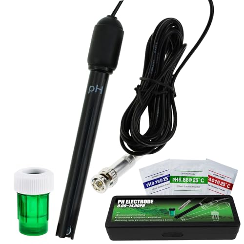
- Long Body, 300cm cable with BNC socket and measure pH range 0.00 – 14.00pH
- Application: water testing in the field, laboratory, pool, spa, hydroponics, aquarium, fish tank and other waste water a…
- Compatibility: Can be use in pH measuring device like pH meter, pH controller that has BNC input terminal
- Why it’s necessary: Built to withstand constant submersion in corrosive nutrient flows, this probe resists fouling and holds calibration longer than standard laboratory glass probes.
- Key Spec: 0 to 14 pH range, withstands up to 100 PSI, Ryton body with double junction.
Installation and Commissioning Procedures
System commissioning validates hydraulic integrity and control logic before live nutrients hit the crop. Rushing this phase guarantees catastrophic leaks and mismatched dosing ratios.
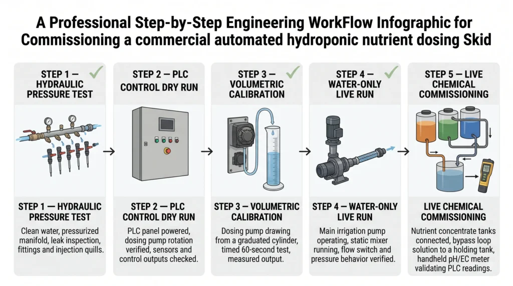
Commissioning a commercial dosing skid is a structured process. You do not connect the acid tanks and turn the system on.
- Hydraulic Pressure Testing: Cap the manifold exit. Hook up a clean water supply and pressurize the skid to 1.5 times its maximum operating pressure. Leave it for two hours. Inspect every threaded fitting, union, and injection quill for micro-leaks. A slow drip at an injection quill will rapidly corrode the skid frame once filled with concentrated acid.
- Control Logic Dry Run: Keep the liquid lines empty. Command the PLC to target an EC of 2.0 and a pH of 5.8. Because the sensors are reading tap water (low EC, high pH), the PLC should trigger the pump relays. Visually confirm the peristaltic pump rotors turn in the correct direction.
- Volumetric Calibration: Place the intake line of Pump A into a graduated cylinder filled with exactly 500 mL of water. Command the PLC to run Pump A for exactly 60 seconds. Measure the remaining water in the cylinder. If 400 mL remains, your pump flow rate is 100 mL/min. Input this exact value into your hydroponic controller software. Repeat for all pumps.
- Water-Only Live Run: Fill your concentrate tanks with plain water. Run the main irrigation pump. Trigger a dosing cycle. Monitor the manifold for vibration or water hammer.
- Live Chemical Commissioning: Introduce the actual nutrient concentrates and acid. Set the PLC targets. Allow the system to run on a bypass loop back into a holding tank. Manually verify the holding tank’s EC and pH with a handheld, calibrated meter. Compare the handheld reading to the PLC display. Adjust the transmitter offset if necessary.
Advanced Troubleshooting and Problem Resolution
When a skid fails, the crop dies fast. Diagnosing flow anomalies, sensor drift, and electrical faults requires a systematic fault tree approach rather than blind guesswork.
Troubleshooting automated skids isolates problems into three categories: hydraulic, electrical, and logic.
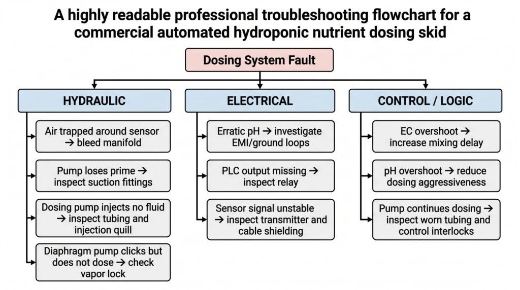
Symptom: The PLC displays an erratic, jumping pH reading.
- Hydraulic Cause: Air bubbles are trapped in the manifold manifold around the probe. Bleed the manifold air release valve. Ensure main pump suction lines have no air leaks.
- Electrical Cause: Ground loop interference. The nutrient solution is carrying stray voltage from a faulty submersible pump. Install a ground loop isolator on the BNC connection between the probe and the transmitter, or ground the water using a titanium grounding rod in the reservoir.
- Maintenance Cause: The probe glass bulb is coated in biofilm or calcium scale. Remove the probe. Clean with a soft brush and a dedicated probe cleaning solution. Recalibrate using 4.0 and 7.0 buffer fluids. See our hydroponic sensors guide for advanced cleaning protocols.
Symptom: The skid continuously overshoots the target EC.
- Logic Cause: The PID (Proportional-Integral-Derivative) control loop tuning is too aggressive. The system injects nutrients, but does not wait long enough for the mixed fluid to reach the sensor. The PLC thinks the EC is still low and injects more. By the time the fluid reaches the sensor, the dose is doubled. Increase the derivative time delay in the PLC settings to allow mixing before the next reading.
- Hydraulic Cause: The dosing pump tubing is worn out. It fails to pinch shut completely, allowing concentrate to siphon past the rollers and drip continuously into the manifold even when the pump is off. Replace the peristaltic tubing.
Symptom: Diaphragm dosing pump clicks loudly but injects no fluid.
- Hydraulic Cause: Vapor lock. Concentrated chemicals like sodium hypochlorite can off-gas inside the suction tubing. The gas bubble enters the pump head. Compressible gas stops the diaphragm from creating suction. Open the pump’s bleed valve to purge the gas while the pump is running until solid fluid appears.
- Hydraulic Cause: Clogged injection quill. The point where the concentrate enters the main manifold features a small check valve (the quill). Minerals precipitate and crystallize at this high-friction point. Remove the quill and soak it in an acidic descaling solution.
For general system faults that extend beyond the skid itself, bookmark our comprehensive hydroponic troubleshooting guide.
Performance Monitoring and Preventative Maintenance
Reactive maintenance destroys profitability. Replacing wear items on a strict schedule prevents emergency downtime and maintains baseline dosing accuracy.
A commercial dosing skid is not a set-it-and-forget-it appliance. Moving parts wear out. Probes drift.
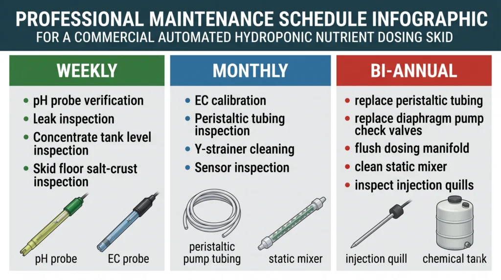
Weekly Tasks:
- Check calibration of pH probes against 7.0 and 4.0 buffer solutions. Do not adjust calibration if the reading is within 0.1 of the buffer; frequent micro-adjustments cause controller instability.
- Visually inspect the floor beneath the skid for salt crusts. Salt accumulation indicates a micro-leak that has dried and crystallized.
- Check concentrate tank levels. Never let a pump run dry, as it ruins the calibration curve when re-primed.
Monthly Tasks:
- Calibrate EC probes using a 2.77 mS/cm standard solution.
- Inspect peristaltic pump tubing. Look for flattening or fatigue where the rollers compress the tube.
- Clean inline Y-strainers upstream of the dosing skid. Restricted main flow alters the injection dynamics.
Bi-Annual Tasks:
- Replace all peristaltic pump tubing regardless of visible wear. The rubber loses elasticity, reducing the volume displaced per rotation.
- Replace check valves on diaphragm pumps.
- Flush the entire dosing manifold with a descaling solution to clear accumulated calcium carbonate and biofilm from the static mixer baffles.
Keep a dedicated spare parts inventory on site. You must stock spare pH probes, replacement peristaltic tubing, spare injection quills, and backup relays. Ordering a replacement pH probe on a Friday night while your system pumps raw acid into a dead zone is an expensive lesson in inventory management.

- 【Easy to use】 Supports °C/°F display.
- 【Dual relay】able to power refrigeration and heating equipment as conditions change.
- 【Dual Display Window】Displays measured temperature and set temperature at the same time.
- Why it’s necessary: While your PLC handles nutrients, managing the ambient temperature of your dosing room prevents chemical crystallization in cold weather. This plug-and-play relay manages space heaters or exhaust fans effortlessly.
- Key Spec: Dual relay output (heating and cooling), 1200W max load, high/low alarms.
Safety Systems and Failsafe Engineering
Automation without hard physical limits guarantees eventual failure. Hardware interlocks must exist outside the software code to sever power when conditions reach hazardous levels.
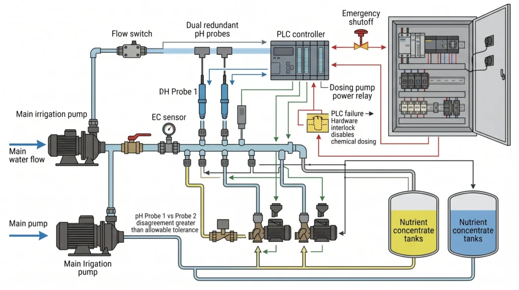
Relying entirely on software to protect your crop is dangerous. If the PLC processor hangs or a solid-state relay fails in the “closed” position, the dosing pump will run continuously until the acid tank is empty.
You must implement physical interlocks. Wire the dosing pump power supply through a flow switch on the main irrigation manifold. If the main pump fails and water stops moving, the flow switch opens the circuit, physically cutting power to the dosing pumps. This prevents the dosing pumps from filling a stagnant manifold with concentrated acid, which would melt the PVC and cause a catastrophic hazardous materials spill.
Install redundant sensors. Commercial setups use two pH probes in the same manifold. The PLC constantly compares Probe 1 against Probe 2. If the readings diverge by more than 0.5 pH, the PLC triggers an alarm and locks out the acid dosing pump. This logic handles the most common failure: a fouled probe reading a falsely high pH, which would normally command the system to dump lethal amounts of acid into the water.
Integrate basic hardware automation like smart contractors to control secondary systems around the skid. Review our notes on smart plugs and timers to handle exhaust fans or mixing agitators independently of the main PLC.
Economic Analysis and Scalability
Capital expenditure on an automated skid provides a measurable return on investment through labor reduction, fertilizer efficiency, and exact yield predictability.
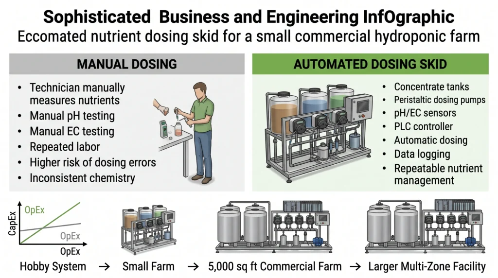
A commercial dosing skid represents a significant capital investment. Systems range from $2,500 for entry-level 4-channel setups to $15,000+ for industrial panels with integrated PLCs and stainless steel manifolds.
You justify this cost through operational expenditure (OpEx) reduction. Hand-dosing a 1,000-gallon system takes an operator roughly 45 minutes of measuring, mixing, testing, waiting, and adjusting. Doing this twice a week consumes 78 hours of labor per year. At $20 an hour, that is $1,560 in direct labor costs wasted on a task a machine does perfectly in seconds.
More importantly, automated dosing prevents nutrient lockouts caused by human error. One botched pH adjustment can stall crop growth for three days. In a facility turning over lettuce every 35 days, a three-day delay equates to an 8% reduction in annual harvest cycles. The skid pays for itself by guaranteeing the harvest timeline.
When planning your initial farm budget, evaluate how different hardware tiers impact long-term profitability by reading our breakdown on hydroponic system upgrades and ROI.
As your farm expands, a properly engineered skid scales with you. Because the sensors read concentration (EC/pH) rather than total volume, you can connect a 5,000-gallon reservoir to the same skid that previously ran a 500-gallon tank. The pumps will simply run longer to achieve the target setpoints. Ensure you purchase nutrient concentrates in bulk totes (275 gallons) rather than 5-gallon jugs to drastically lower your cost per pound of fertilizer. To understand bulk nutrient profiles, study our hydroponic nutrients guide.
Frequently Asked Questions
Can I mix calcium nitrate and magnesium sulfate in the same concentrate tank to save money on dosing pumps?
No. Mixing concentrated calcium and sulfates causes an immediate precipitation reaction, forming solid calcium sulfate (gypsum). This white sludge will permanently clog your dosing pumps, injection quills, and manifold. You must maintain Tank A (Calcium/Iron) and Tank B (Sulfates/Phosphates) separately and inject them into the flowing water stream independently.
Why does my pH reading drop drastically when my main irrigation pump turns on?
This is a classic symptom of ground loop interference. The main water pump is leaking a tiny amount of stray voltage into the water. The pH probe reads this voltage difference, misinterpreting it as an acidic shift. Install a BNC ground loop isolator on your pH probe cable, or install a titanium grounding rod in your reservoir wired directly to the earth ground.
How do I prevent vapor lock in my diaphragm dosing pump using sodium hypochlorite (bleach)?
Sodium hypochlorite naturally off-gasses inside suction tubing, creating bubbles that stall diaphragm pumps. Use an auto-degassing pump head that features a continuous internal bleed valve, returning a small amount of liquid and gas back to the concentrate tank while pushing the liquid forward into the manifold. Keep the suction tubing as short and vertical as possible.
What is the difference between a pulse-controlled pump and a 4-20mA controlled pump?
A pulse-controlled pump receives discrete digital signals (pulses) from the PLC. Each pulse triggers one mechanical stroke of the pump. The PLC controls the volume by varying the frequency of the pulses. A 4-20mA controlled pump receives a continuous analog current. The pump speeds up or slows down its motor dynamically based on the current level (e.g., 4mA = 0 RPM, 20mA = Max RPM). Analog control provides smoother injection profiles for high-flow systems.
Should I place the injection quills before or after the main system water filter?
Always place injection quills downstream of your primary mechanical filtration. If you inject concentrated salts upstream of a 100-micron screen filter, any minor localized precipitation will get caught in the mesh. This rapidly clogs the filter, dropping system pressure and starves the crop of water. The order should be: Main Pump -u003e Filter -u003e Flow Switch -u003e Injection Quills -u003e Static Mixer -u003e Sensors.
Conclusion
Transitioning to commercial automated nutrient dosing skids removes the largest bottleneck in small farm production: manual water chemistry management. By engineering a robust manifold, calculating precise fluid dynamics, and implementing fail-safe PLC logic, you transform your irrigation room from a liability into a highly controlled asset. Stop guessing with hand-held meters and manual pitchers. Automate your feed, protect your margins, and scale your canopy.
For the next step in optimizing your facility’s water delivery, utilize our hydroponic nutrient calculator to lock in your exact elemental parts per million before configuring your new skid inputs.

Continue Your Learning Journey