DIY Aeroponic High-Pressure Misting Manifold with 1000 PSI Solenoids

Table of Contents
- The Physics of True High-Pressure Aeroponics (HPA)
- System Architecture and Component Blueprint
- Mathematical Sizing and Fluid Dynamics Calculations
- Step-by-Step DIY Manifold Fabrication Guide
- Precision Automation: Short-Cycle Timers and Pulse Tuning
- Nutrient Chemistry and Nozzle Clogging Prevention
- Exhaustive Troubleshooting Guide: Diagnosing HPA Failures
- Frequently Asked Questions
- Accumulator Cycle Estimator
- System Verification and Strategic Next Steps
Disclosure: MistCulture summarizes verified product specs, engineering data, and community feedback. We may earn an affiliate commission if you purchase through our links. Regulations vary by location; this content is for educational purposes only.
True High-Pressure Aeroponics (HPA) operates on a distinct physical principle from standard hydroponic irrigation: atomizing a nutrient solution into suspended droplets between 30 and 80 microns in diameter. Low-pressure aeroponic (LPA) setups rely on aquarium pumps and irrigation sprinklers that generate heavy droplets exceeding 200 microns. Those oversized droplets saturate root mats, strip away delicate root hairs, and create the same waterlogged conditions found in poorly drained soil. HPA systems deliver a pressurized, oxygen-saturated nutrient fog directly to bare root systems. The result is explosive root velocity, shorter crop cycles, and near-zero water waste.
Designing a reliable DIY high-pressure misting manifold requires precision plumbing, accumulator tank hydraulics, industrial solenoid automation, and rigorous fluid math. Connecting a high-pressure booster pump directly to a line of misting nozzles will cause premature pump failure and uneven droplet sizing. Because diaphragm pumps take several seconds to build operating pressure, direct-plumbed nozzles drool large droplets at the start and end of every cycle. Rapid short-cycle pulsing also burns out pump pressure switches within weeks.
This engineering guide provides the blueprints, mathematical calculations, and mechanical assembly steps required to build a commercial-grade HPA misting manifold. By integrating an accumulator tank with high-pressure solenoids, your system will deliver instant, crisp 50-micron atomization while running the primary pump only twice per day.
The Physics of True High-Pressure Aeroponics (HPA)
True HPA requires line pressures between 80 and 100 PSI to generate 30-to-80-micron droplets. Droplets smaller than 30 microns drift away without depositing nutrients, while droplets larger than 100 microns create waterlogged root mats that invite anaerobic pathogens.
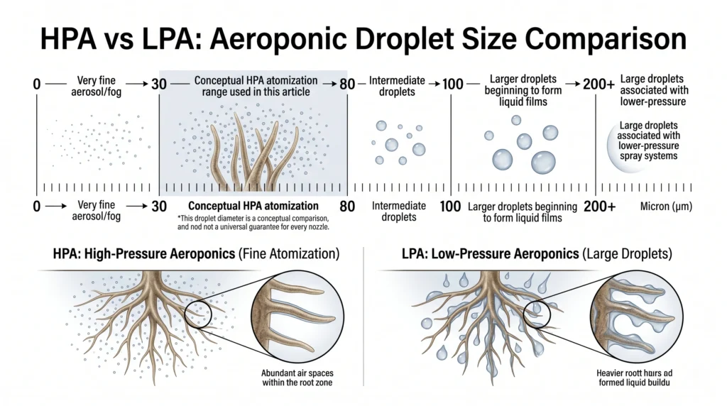
Root hair diameters in fast-growing annual crops like lettuce, tomatoes, and peppers range from 10 to 15 microns. When an irrigation droplet is too large, it hits the root hair with excessive kinetic energy, shearing the single-cell structure and forcing the plant to rebuild its absorbing root tips. Once an oversized droplet condenses on the root shaft, it forms a thick liquid film that restricts atmospheric oxygen exchange.
| Droplet Size | Classification | Root-Zone Impact |
|---|---|---|
| 0–30 Micron | Dry Fog / Aerosol | Drifts away; poor nutrient impact |
| 30–80 Micron | TRUE HPA RANGE | Ideal root-hair absorption and oxygen availability |
| 80–100 Micron | Upper Acceptable Threshold | Acceptable for mature roots |
| 100–200 Micron | Transition Zone | Droplets coalesce into liquid films |
| 200+ Micron | Low-Pressure Sprinklers | Root shear and waterlogging risk |
To achieve the ideal 50-micron droplet target, water must be forced through a precision micro-orifice (typically 0.008 to 0.016 inches in diameter) at high pressure. Line pressure directly governs atomization quality. At 40 PSI, a standard 0.012-inch misting nozzle emits an uneven spray with droplets averaging 140 microns. At 80 to 100 PSI, that same orifice produces an even, suspended fog averaging 50 microns.
In enterprise agricultural facilities and research chambers, custom stainless steel manifolds operate at pressures up to 1,000 PSI using specialized hydraulic plungers. For advanced DIY builders, an operating pressure of 80 to 100 PSI represents the sweet spot of hydraulic efficiency, component affordability, and biological performance. When comparing DWC vs NFT vs Aeroponics, this precise droplet sizing is the primary reason true HPA systems achieve up to 30% faster biomass accumulation than recirculating water culture.

- This pump kit includes Aquatec high flow booster pump 8852-2J03-B424 with heavy duty steel base plate with damper, PSW-3…
- This pump is designed to increase the water supply pressure to a RO water system. Increase input pressure from 30-40 psi…
- This kit is good for 1/4″ OD tubing or 3/8″ OD tubing since we include 3/8″ to 1/4″ reducer fittings for pump and for pr…
- Why it’s necessary: The Aquatec 8800 is the industry-standard diaphragm pump for HPA builds, capable of maintaining 100+ PSI continuous line pressure without the thermal cutoff failures common in standard RO booster pumps.
- Key Spec: 130 PSI maximum pressure / 24V DC continuous duty cycle / 3/8-inch push-to-connect ports.
System Architecture and Component Blueprint
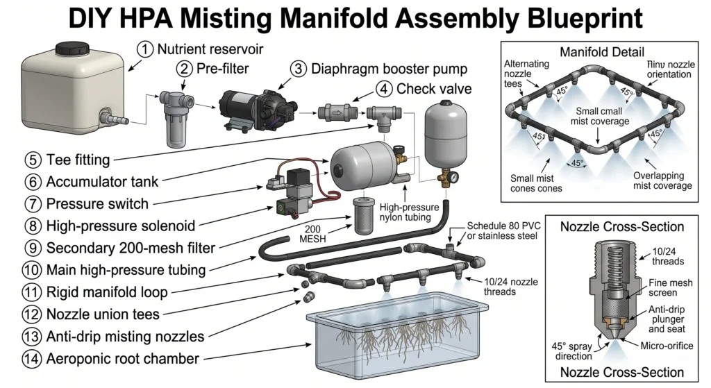
A professional HPA manifold decouples the pump from the nozzles using a pressurized accumulator tank and an inline solenoid valve. This architecture eliminates pressure ramp-up drool and extends pump switch lifespan from weeks to years.
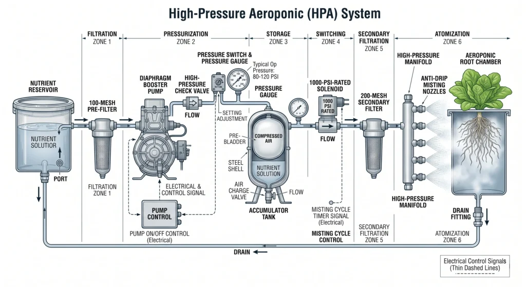
A closed-loop high-pressure aeroponic system consists of six distinct hydraulic zones:
- Pre-Filtration Zone: Nutrient solution is drawn from the primary reservoir through a 100-mesh (149-micron) stainless steel sediment strainer. This prevents coarse undissolved salts and organic debris from reaching the pump valves.
- Pressurization Zone: A positive-displacement diaphragm pump elevates the fluid pressure to 100 PSI. A high-pressure check valve installed immediately downstream prevents pressurized water from flowing backward through the pump head when the motor rests.
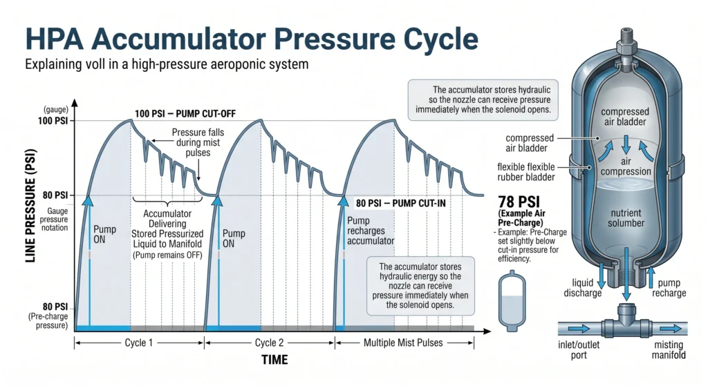
- Hydraulic Storage Zone: Pressurized fluid enters a pre-charged bladder accumulator tank. An adjustable pressure switch wired in line with the pump power supply monitors tank pressure. When the tank reaches 100 PSI, the switch cuts power to the pump. When pressure drops to 80 PSI, the switch restarts the motor.
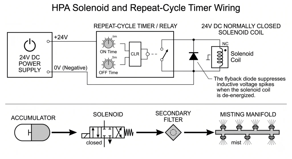
- Precision Switching Zone: A zero-differential, normally closed (N.C.) solenoid valve sits between the accumulator tank and the root chamber manifold. When signaled by a repeat-cycle timer, the solenoid snaps open in less than 20 milliseconds, delivering full accumulator pressure instantly to the nozzles.
- Secondary Filtration Zone: A inline 200-mesh (74-micron) screen filter sits between the solenoid and the misting nozzles to catch any micro-coagulation or biofilm fragments before they reach the 50-micron nozzle orifices.
- Atomization Manifold: Rigid Schedule 80 PVC, stainless steel, or high-density nylon tubing distributes the pressurized fluid to precision anti-drip misting nozzles oriented around the root chamber.
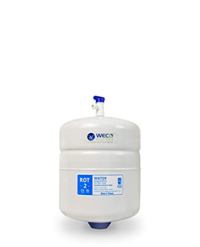
- ✅𝗥𝗘𝗟𝗜𝗔𝗕𝗟𝗘 𝗪𝗔𝗧𝗘𝗥 𝗣𝗥𝗘𝗦𝗦𝗨𝗥𝗜𝗭𝗔𝗧𝗜𝗢𝗡: This pressurized water storage tank integrates with your reverse osmosis (RO) water filt…
- ✅𝗣𝗥𝗘𝗠𝗜𝗨𝗠 𝗦𝗔𝗙𝗘𝗧𝗬 𝗔𝗡𝗗 𝗗𝗨𝗥𝗔𝗕𝗜𝗟𝗜𝗧𝗬: This reverse osmosis tank features an FDA-grade polypropylene liner, a high-grade butyl …
- ✅𝗘𝗡𝗛𝗔𝗡𝗖𝗘𝗗 𝗣𝗘𝗥𝗙𝗢𝗥𝗠𝗔𝗡𝗖𝗘 𝗟𝗢𝗡𝗚𝗘𝗩𝗜𝗧𝗬: Pre-charged to 7 psi with compressed nitrogen, the RO tank ensures stable air pressure …
- Why it’s necessary: Storing pressurized nutrient solution in an accumulator tank allows instant, crisp nozzle discharge without waiting for pump mechanical spin-up, preventing root-killing droplet drool.
- Key Spec: 2.0-gallon total volume / Food-grade butyl bladder / Stainless steel 1/4-inch NPT connector.
Mathematical Sizing and Fluid Dynamics Calculations
Guessing manifold flow rates or accumulator tank dimensions leads to pressure drops during misting pulses. Calculate your exact nozzle consumption (
Q_total), usable bladder drawdown (V_drawdown), and pulse frequency (N_pulses) before cutting any tubing.
Calculation 1: Manifold Flow Rate and Nozzle Sizing
To size your main feed lines and verify accumulator capacity, calculate the total volumetric flow rate (Q_total) of your misting manifold. Standard 0.012-inch (0.3 mm) anti-drip misting nozzles discharge 0.015 gallons per minute (GPM) at 80 PSI.
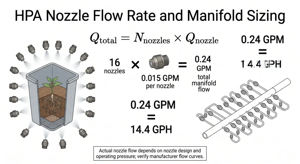
The formula for total manifold flow rate is:
Q_total = N_nozzles * Q_nozzle
Where:
Q_total= Total manifold flow rate in gallons per minute (GPM)N_nozzles= Total number of active nozzles in the root chamberQ_nozzle= Flow rate of a single nozzle at operating pressure (0.015 GPM at 80 PSI)
Worked Engineering Example:
A vertical aeroponic build requires 16 nozzles to ensure 360-degree root coverage across 4 chambers.
Q_total = 16 * 0.015 GPM
Q_total = 0.24 GPM (or 14.4 gallons per hour, GPH)
Calculation 2: Accumulator Tank Usable Draw-Down Volume
A 2-gallon accumulator tank does not hold 2 gallons of usable water. The interior contains a compressed air bladder that occupies most of the internal volume. Usable water capacity—the draw-down volume (V_drawdown)—is governed by Boyle’s Law applied to hydropneumatic bladders.
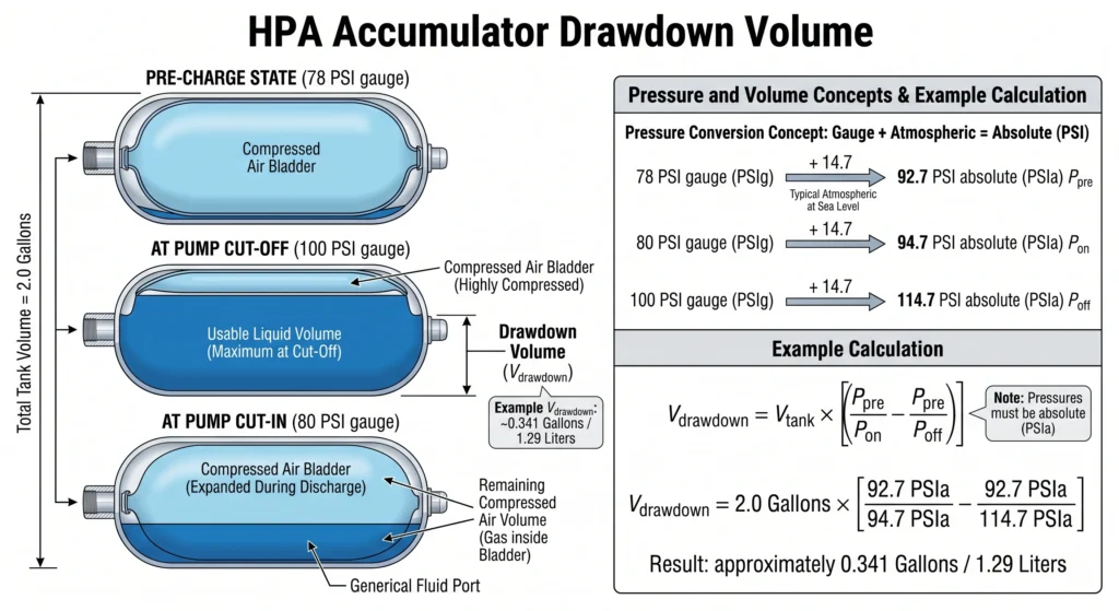
The formula for draw-down volume is:
V_drawdown = V_tank * ((P_pre / P_on) - (P_pre / P_off))
Where:
V_drawdown= Usable water volume delivered between pump cycles (Gallons)V_tank= Total physical volume of the accumulator tank (2.0 Gallons)P_pre= Air pre-charge pressure in the bladder expressed as Absolute Pressure (PSI_gauge + 14.7)P_on= Pump cut-on pressure (80 PSI gauge + 14.7 = 94.7 PSI absolute)P_off= Pump cut-off pressure (100 PSI gauge + 14.7 = 114.7 PSI absolute)
For optimal HPA operation, set the air pre-charge (P_pre) to 2 PSI below the pump cut-on pressure:
78 PSI gauge + 14.7 = 92.7 PSI absolute
Worked Engineering Example:
Let us calculate the usable misting water delivered by a 2.0-gallon tank cycling between 80 PSI and 100 PSI:
V_drawdown = 2.0 * ((92.7 / 94.7) - (92.7 / 114.7))
V_drawdown = 2.0 * (0.9788 - 0.8081)
V_drawdown = 2.0 * 0.1707
V_drawdown = 0.3414 gallons (approx. 1.29 liters of high-pressure fluid)
Calculation 3: Misting Pulse Timing and Pump Cycle Intervals
Now determine how much water is consumed during a single misting pulse (V_pulse) and how many pulses the system can execute before the booster pump motor switches on.
The formula for pulse volume is:
V_pulse = Q_total * (t_on / 60)
Where:
V_pulse= Volume of water consumed per misting pulse (Gallons)Q_total= Total manifold flow rate (0.24 GPM)t_on= Mist pulse ON duration in seconds (2.0 seconds)
Worked Engineering Example:
V_pulse = 0.24 GPM * (2.0 / 60)
V_pulse = 0.24 * 0.0333
V_pulse = 0.008 gallons per pulse (approx. 30.2 milliliters)
To calculate the number of misting pulses (N_pulses) delivered per pump cycle:
N_pulses = V_drawdown / V_pulse
N_pulses = 0.3414 gallons / 0.008 gallons
N_pulses = 42.67 pulses
If your aeroponic timer is set to mist for 2 seconds every 3 minutes (180 seconds OFF), one pulse occurs every 3.03 minutes.
Total rest time between pump runs = 42.67 pulses * 3.03 minutes = 129.28 minutes
Your booster pump will only turn on once every 2 hours and 9 minutes, running for approximately 35 seconds to recharge the tank. This eliminates pressure switch chatter and prevents electrical overheating. To check your timing ratios against crop growth stages, use our Aeroponic Mist Timer Calculator.

- 1/4″ SOLENOID VALVE, 12V DC: A 1/4″ stainless steel electric high-pressure solenoid valve, normally closed, delivers fas…
- STAINLESS STEEL BODY, PEEK SEAL: A durable stainless steel body and PEEK seal resist corrosion and handle demanding medi…
- NORMALLY CLOSED: The valve stays shut with no power and opens only when energized, so flow stops safely on power loss fo…
- Why it’s necessary: Standard plastic irrigation solenoids require a 3-to-5 PSI differential drop to open and fail under 100+ PSI HPA pressures. A zero-differential industrial valve opens instantaneously under direct electrical signal.
- Key Spec: 1000 PSI max pressure / 110V AC or 24V DC coil / Viton corrosion-resistant diaphragm.
Step-by-Step DIY Manifold Fabrication Guide
Building a leak-free 100 PSI manifold requires rigid plumbing materials, clean cuts, and correct mechanical assembly. Follow this sequence to assemble your pump skid, accumulator integration, and misting chamber distribution lines.
Component and Hardware Manifest
- Pump: Aquatec 8800 (130 PSI bypass, 3/8-inch ports) with 24V DC power transformer.
- Accumulator Tank: 2-to-5 gallon hydropneumatic RO tank with standard Schrader air valve.
- Pressure Switch: Aquatec upper-limit pressure switch (preset or adjustable 80-100 PSI) wired in series with the pump transformer low-voltage lead.
- Check Valve: 3/8-inch push-to-connect non-return check valve (stainless steel internal spring).
- Solenoid Valve: 1/4-inch NPT or 3/8-inch NPT stainless steel normally closed (N.C.) solenoid valve rated for 0-1000 PSI.
- Tubing: High-pressure LLDPE (Linear Low-Density Polyethylene) or nylon tubing rated for 150+ PSI working pressure (3/8-inch OD for main lines, 1/4-inch OD for nozzle branches).
- Nozzles: 0.012-inch (0.3 mm) anti-drip misting nozzles with 10/24 UNC threads and built-in polypropylene filters.
- Fittings: John Guest push-to-connect tees, elbows, and 10/24 threaded nozzle union tees.
- Thread Sealant: PTFE Teflon tape and liquid pipe thread sealant (food-grade).
Step 1: Pre-Charge Accumulator Bladder Calibration
Before introducing water to the system, calibrate the air pressure inside the accumulator tank. Use a standard bicycle tire pressure gauge and a floor pump.
- Unscrew the blue or black dust cap covering the Schrader air valve on the bottom of the accumulator tank.
- Measure the factory pre-charge. Standard RO tanks ship with 7 to 10 PSI of air pressure.
- Attach a bicycle pump or compressor and inflate the dry bladder to 78 PSI (exactly 2 PSI below your 80 PSI pump cut-on threshold).
- Verify the pressure with a digital gauge. Replace the dust cap securely to prevent slow valve leaks.
Step 2: High-Pressure Pump Skid Assembly
Assemble the pump, pressure switch, and accumulator on a vibration-damped mounting board (3/4-inch exterior plywood with rubber feet).
- Mount the Aquatec 8800 pump horizontally using rubber isolation washers to dampen mechanical hum.
- Install a 3/8-inch push-to-connect check valve on the OUTLET port of the pump. Ensure the flow arrow points away from the pump head.
- Connect a short 3/8-inch LLDPE tubing loop from the check valve outlet to a push-to-connect Tee fitting.
- Connect branch A of the Tee to the 1/4-inch stainless steel port of the accumulator tank using a 3/8-inch push-to-connect to 1/4-inch female NPT adapter. Wrap the NPT threads with 4 wraps of PTFE tape before tightening.
- Install the Aquatec inline pressure switch on branch B of the Tee. Connect the electrical leads of the pressure switch in series with the positive (red) wire of the 24V DC pump power supply.
Step 3: Solenoid and Secondary Filtration Wiring
- Run a 3/8-inch LLDPE tube from the pressure switch outlet to the INLET port of the stainless steel solenoid valve. Use NPT-to-push-to-connect adapters sealed with PTFE tape.
- Wire the solenoid coil to your digital repeat-cycle timer. If using a 24V DC solenoid, install a 1N4007 flyback diode across the positive and negative terminals. This absorbs the inductive voltage spike generated when the magnetic coil collapses, protecting solid-state timer relays from short-circuiting.
- Install the 200-mesh secondary screen filter immediately downstream of the solenoid OUTLET port.
Step 4: Rigid Misting Manifold Fabrication
For the root chamber interior, build a closed-loop rigid manifold using Schedule 80 PVC or flexible high-pressure nylon lines secured with stainless steel Adel clamps.
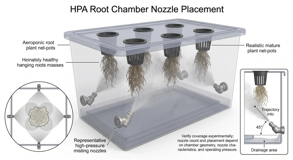
- Design a square or rectangular loop around the upper perimeter of the root chamber, keeping the manifold 4 to 6 inches below the net pot bottoms.
- Install push-to-connect nozzle union tees every 8 to 10 inches along the manifold line.
- Thread the 0.012-inch anti-drip misting nozzles into the 10/24 UNC ports on the tees. Tighten by hand, then apply a quarter-turn with an open-end wrench. Do not over-tighten, as brass threads snap easily inside acetal fittings.
- Nozzle Vectoring: Offset alternate nozzles at 45-degree downward angles relative to the root mass. Directing 100 PSI mist straight into hanging roots at close range causes physical shear damage. Vectoring the spray creates a swirling, highly oxygenated vortex of fog that coats root hairs uniformly without mechanical injury.
Recommended: 50-Micron Anti-Drip Misting Nozzles with Internal Filter
- Why it’s necessary: Built-in stainless steel check valves stop water flow the millisecond line pressure drops below 30 PSI, preventing after-spray droplets that cause root suffocation.
- Key Spec: 0.012-inch (0.3mm) orifice / 10/24 UNC thread / Integrated washable sintered filter.
- Check current pricing on Amazon:
[https://www.amazon.com/dp/B08BLHN372](https://www.amazon.com/dp/B08BLHN372)
Precision Automation: Short-Cycle Timers and Pulse Tuning
Standard hydroponic timers with 1-minute minimum intervals are incompatible with High-Pressure Aeroponics. A 60-second spray cycle saturates root mats, strips away root hairs, and creates anaerobic conditions.
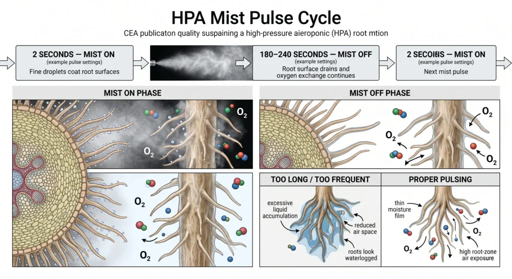
In true HPA, irrigation timing is managed in milliseconds and seconds. The goal is to apply a microscopic film of nutrient solution to the root hairs, then immediately stop the spray so the root tissue can absorb oxygen from the surrounding vapor. As the roots transpire and assimilate the film, another micro-burst of fog restores moisture before the root hairs dry out.
HPA Irrigation Pulse Cycle
- [ ON: 1-3 Seconds ] ➔ Atomized fog coats root hairs (No runoff)
- [ OFF: 3-5 Minutes ] ➔ Maximum atmospheric oxygen absorption
Selecting an Industrial Repeat-Cycle Timer
Avoid standard mechanical pin timers and basic smart plugs. Use an industrial digital repeat-cycle timer capable of independent ON and OFF settings down to 1-second resolution (such as the Techbee or Inkbird digital cycle timers), or an industrial programmable logic controller (PLC).
When configuring your timer, use these baseline intervals based on crop maturity:
| Growth Stage | Target Crop Stage | Pulse ON Duration | Pulse OFF Duration | 24-Hour Pulse Total |
| Stage 1: Propagation | Clones & Young Seedlings | 1.5 Seconds | 180 Seconds (3 Min) | 480 Pulses |
| Stage 2: Vegetative | Active Leaf & Root Mat Growth | 2.0 Seconds | 240 Seconds (4 Min) | 360 Pulses |
| Stage 3: Heavy Bloom | High-Transpiration Fruiting | 3.0 Seconds | 180 Seconds (3 Min) | 480 Pulses |
| Stage 4: Night / Dark | Lights-Off Respiration | 1.5 Seconds | 360 Seconds (6 Min) | 240 Pulses |
Tuning Mist Intervals Using Environmental Data
Your ON/OFF intervals should not remain static throughout the entire season. They must adjust dynamically based on atmospheric evaporation demand. When Vapor Pressure Deficit (VPD) is high (hot, dry air), aerial transpiration increases, requiring shorter OFF intervals (2 to 3 minutes) to prevent root tip desiccation. When lights switch off and VPD drops, extend the OFF interval to 6 or 8 minutes to prevent root chamber condensation and pooling.
To verify whether your timer settings are dialed in correctly, inspect the floor of your root chamber. If you see deep pools of liquid draining continuously, your ON pulse is too long or your OFF interval is too short. A properly tuned HPA chamber produces a light, humid condensation on the chamber walls and minimal liquid runoff at the chamber drain.
Nutrient Chemistry and Nozzle Clogging Prevention
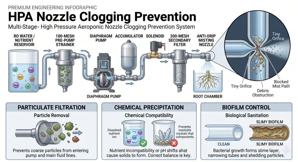
Forcing mineral fertilizers through a 0.008-inch orifice at 100 PSI creates a high risk of chemical precipitation and nozzle failure. Standard greenhouse fertilizers will crystallize and plug an HPA manifold within days.
1. Water Source and Electrical Conductivity (EC) Limits
Always use Reverse Osmosis (RO) water as your base fluid. Municipal tap water contains calcium carbonate and silicates that combine with sulfates in hydroponic fertilizers to form insoluble gypsum crystals. In HPA systems, run lower nutrient concentrations than you would use in Deep Water Culture (DWC) or Nutrient Film Technique (NFT). Because 50-micron droplets coat root hairs directly without competing with bulk water volumes, high nutrient concentrations cause leaf tip burn and root toxicity.
- Leafy Greens / Herbs: Target an Electrical Conductivity (EC) of 1.0 to 1.4 mS/cm.
- Fruiting Crops (Tomatoes / Peppers): Target an EC of 1.6 to 2.0 mS/cm. Never exceed 2.2 mS/cm in high-pressure misting setups.
- For crop-specific feeding schedules and baseline EC targets, refer to our Hydroponic Nutrient Schedule Guide.
2. Fertilizer Selection: Clean Mineral Salts Only
Never use organic fertilizers, kelp extracts, guanos, or suspension blends in an HPA system. Organic inputs rely on biological solids that coagulate under pressure and clog 50-micron orifices instantly. Use 100% water-soluble mineral salts (such as Masterblend, Jack’s 321, or Athena Pro line). Ensure your calcium nitrate and magnesium sulfate are fully dissolved in separate stock containers before combining them in the main reservoir. To prevent mineral lockout and scale buildup, check our Hydroponic pH and EC Mastery Guide.
3. Trace Metal Chelation: DTPA vs EDTA Iron
Standard EDTA iron chelate degrades rapidly at pH levels above 6.2, precipitating out of solution as iron oxide (rust) that binds to nozzle filter screens. For high-pressure manifolds, use DTPA-chelated iron (stable up to pH 7.5) or EDDHA-chelated iron (stable up to pH 9.0). This keeps iron molecules suspended in solution, preventing chemical scaling across precision orifices.
4. Continuous Biological Sanitation with Hypochlorous Acid (HOCl)
Biofilm, the slimy matrix produced by bacteria and fungi; is the leading cause of aeroponic nozzle clogging. Standard hydrogen peroxide (H2O2) degrades within 24 hours in warm reservoirs and can bubble out of solution inside pressurized bladders.
Inject Hypochlorous Acid (HOCl) at a continuous rate of 0.5 to 1.0 PPM (2 to 5 mL per gallon of standard 0.028% horticultural HOCl solution). HOCl is a neutral-pH, non-toxic oxidizer that eliminates biofilm, kills Pythium zoospores, and keeps internal nozzle micro-screens clean without damaging fragile root hairs. To learn more about eliminating waterborne pathogens, review our Hydroponic Root Rot Prevention protocol.
Exhaustive Troubleshooting Guide: Diagnosing HPA Failures
When an HPA system malfunctions, you have hours, not days to diagnose and correct the hydraulic or electrical failure before root desiccation causes permanent crop damage.
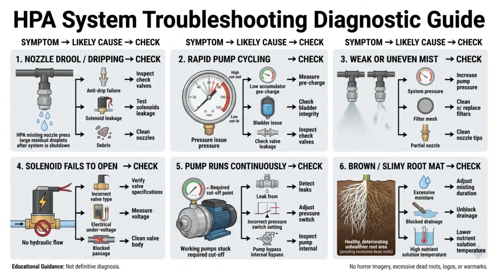
| Symptom | Root Cause | Actionable Engineering Fix |
| Nozzles drool or drip after solenoid closes | 1. Failed anti-drip check spring in nozzle. 2. Solenoid valve seat worn or fouled with debris. 3. Solenoid installed backward (flow arrow reversed). | 1. Soak nozzles in 50% white vinegar for 2 hours; replace if spring is weak. 2. Disassemble solenoid, inspect diaphragm for grit, and flush with RO water. 3. Verify solenoid directional flow arrow points toward misting manifold. |
| Booster pump cycles ON every 2-3 pulses | 1. Accumulator air pre-charge pressure is too low or flat. 2. Accumulator bladder has ruptured. 3. Check valve leaking back into pump head. | 1. Shut off pump, drain liquid pressure to zero, and pressurize air valve to 78 PSI. 2. Depress Schrader air valve; if water sprays out, replace accumulator tank. 3. Replace 3/8-inch push-to-connect check valve on pump outlet port. |
| Pump chatters rapidly (kicks ON/OFF every second) | 1. Pressure switch differential bandwidth is too narrow. 2. Air trapped inside pump head or pressure switch chamber. 3. No accumulator tank installed in hydraulic loop. | 1. Adjust Allen screw on Aquatec pressure switch clockwise 1/4 turn to widen deadband. 2. Loosen outlet fitting slightly while pump runs to bleed trapped air bubbles. 3. Mandatory: Install 2-gallon accumulator tank between pump and solenoid. |
| Misting fog is weak, spitting, or uneven | 1. Operating line pressure has dropped below 60 PSI. 2. Clogged 200-mesh secondary screen filter. 3. Partial calcium/salt precipitation inside nozzle orifice. | 1. Adjust booster pump bypass screw clockwise to increase line pressure to 90 PSI. 2. Unscrew secondary filter canister, remove stainless screen, and acid-wash. 3. Remove affected nozzles and ultrasonic clean in 5% phosphoric or citric acid. |
| Solenoid fails to open (clicks but no spray) | 1. Pilot-operated solenoid used instead of zero-differential. 2. Electrical transformer under-voltage (e.g., 18V on 24V coil). 3. Debris blocking internal pilot orifice of solenoid diaphragm. | 1. Replace with direct-lift zero-differential solenoid rated for 1000 PSI. 2. Check power supply voltage with multimeter under load; replace power supply. 3. Disassemble valve body and clear micro-channel with compressed air. |
| Pump runs continuously without shutting off | 1. Severe leak in pressurized tubing or manifold fittings. 2. Pressure switch cut-off threshold set higher than pump max PSI. 3. Pump internal diaphragm bypass valve stuck open. | 1. Inspect all John Guest push-to-connect fittings and tubing cuts for squareness. 2. Turn pressure switch adjustment screw counter-clockwise to lower shut-off to 100 PSI. 3. Rebuild pump head with Aquatec diaphragm replacement kit. |
| Root mat turns brown and slimy at bottom of chamber | 1. Misting pulses too long (>5 seconds), causing waterlogging. 2. Chamber drainage port clogged, causing roots to sit in runoff. 3. Nutrient solution temperature exceeding 75°F (24°C). | 1. Reprogram cycle timer to 2 seconds ON / 4 minutes OFF. 2. Elevate root chamber bottom and clear 1-inch drain lines of root debris. 3. Add an inline hydroponic water chiller to keep reservoir at 65°F (18°C). |
For additional diagnostic support on plant stress, leaf symptoms, and nutrient lockout, refer to our comprehensive Hydroponic Troubleshooting Guide.
Frequently Asked Questions
What is the difference between Low-Pressure Aeroponics (LPA) and High-Pressure Aeroponics (HPA)?
LPA uses standard aquarium Mag-Drive pumps operating at 5 to 15 PSI to spray water through irrigation sprinkler heads. This produces large water droplets (u003e200 microns) that soak roots like a shower, offering results similar to Deep Water Culture. True HPA uses a positive-displacement diaphragm pump operating at 80 to 100 PSI to push liquid through 0.012-inch orifices. This creates an atomized fog (30–80 microns) that coats root hairs without impeding atmospheric oxygen exchange.
Why do I need an accumulator tank for an aeroponic system?
A booster pump cannot spin up to 100 PSI instantly. Without an accumulator tank, line pressure ramps up slowly over several seconds, causing nozzles to spit large, watery drops before reaching misting pressure. When the timer shuts off, pressure bleeds down slowly, causing after-drip. An accumulator tank stores pre-pressurized water. When the inline solenoid opens, 100 PSI pressure is delivered to the nozzles instantaneously, producing crisp 50-micron atomization from millisecond zero to valve closure.
How do I prevent aeroponic misting nozzles from clogging?
Prevent clogging by maintaining a strict three-tier filtration and chemistry protocol:u003cbru003e- Use a 100-mesh pre-pump strainer and a 200-mesh post-solenoid screen filter.u003cbru003e- Use only 100% water-soluble mineral salts mixed with Reverse Osmosis (RO) water, never use organic fertilizers or thick supplements.u003cbru003e- Add u003cstrongu003eHypochlorous Acid (HOCl)u003c/strongu003e at 0.5 PPM continuously to oxidize biofilms inside the plumbing lines before they reach the nozzle orifices.
Can I use a standard 24-hour mechanical timer for HPA?
No. Standard mechanical timers have minimum ON intervals of 15 minutes, while standard digital smart plugs have minimum ON intervals of 1 minute. Running an HPA misting manifold for 60 seconds continuously will waterlog roots and strip away delicate root hairs. You must use a digital repeat-cycle timer or PLC capable of 1-second resolution (e.g., 2 seconds ON, 180 seconds OFF).
What pipe material is best for an HPA misting manifold?
Use Schedule 80 PVC (grey), stainless steel tubing, or high-pressure nylon/LLDPE tubing rated for at least 150 PSI working pressure. Do not use thin-walled Schedule 40 PVC or flexible silicone drip tubing. Thin-walled pipes flex under 100 PSI pressure spikes, which causes push-to-connect fittings to blow out and threaded nozzle ports to fracture.
How many nozzles do I need per aeroponic root chamber?
Install enough nozzles to create a uniform, overlapping fog vortex without spraying directly into the center root mass at close range. For a standard 27-gallon tote chamber, use 4 nozzles positioned in the upper corners, angled 45 degrees downward and slightly off-center. This creates a swirling cyclone of mist that surrounds the hanging roots without mechanical shear.
Why is my high-pressure solenoid valve getting hot to the touch?
Solenoid coils generate electrical resistance heat when energized. In HPA setups, the solenoid is only energized for 2 to 3 seconds per cycle, so it should remain cool. If your solenoid is getting hot, your timer is programmed incorrectly (leaving the valve open too long), or you are using an AC coil on a DC power supply. Ensure you use an industrial continuous-duty solenoid matched correctly to your power voltage.
Accumulator Cycle Estimator
Estimate roughly how many misting bursts your accumulator tank can supply before the pump needs to kick back on and refill it.
Estimate how many misting bursts your accumulator tank delivers before the pump needs to refill it. Uses the standard bladder-tank drawdown formula (based on Boyle’s Law) that well and RO system manufacturers use for the same calculation.
This is a physics-based estimate (bladder tank drawdown via Boyle’s Law), not an exact guarantee, real nozzle flow, temperature, and tank efficiency all introduce some variance. Confirm your pre-charge with a tire gauge on an empty tank before relying on this.
System Verification and Strategic Next Steps
Building a true High-Pressure Aeroponic misting manifold moves your growing operation from basic water recirculation into precision agricultural engineering. By maintaining line pressures between 80 and 100 PSI, sizing your accumulator bladder correctly, and automating your misting intervals in seconds, you provide plant roots with the ultimate balance of water, nutrients, and atmospheric oxygen.
Before introducing live crops to your new HPA build, run a 48-hour hydraulic pressure test with pure Reverse Osmosis water. Check all push-to-connect fittings for micro-leaks, verify that your accumulator tank holds its 78 PSI air pre-charge, and confirm that your nozzles shut off instantly without after-drip when the solenoid closes. Once your hydraulic integrity is confirmed, you can calibrate your nutrient profile and introduce your crops to high-performance atomization.
To expand your hydroponic and aeroponic engineering setups, explore our specialized design guides and calculation tools:
- Sizing commercial towers and vertical layouts: DIY Aeroponic Tower Blueprint
- Comparing root zone dynamics: DWC vs NFT vs Aeroponics Guide
- Calibrating sensor arrays and automation hardware: Hydroponic Sensors Guide
- Comprehensive overview of soilless cultivation: Growing Systems Hub

Continue Your Learning Journey