Advanced Hydroponic Systems Engineering and Design

Table of Contents
- Hydroponic System Design Principles and Fluid Dynamics
- Component Selection and Material Specifications
- Environmental Control Engineering
- Nutrient Management Protocols and Chemistry
- Installation, Commissioning, and Calibration Procedures
- Operation, Maintenance, and System Troubleshooting
- Commercial Scaling, Economic Analysis, and ROI
- Safety Systems and Redundancy Architecture
- Frequently Asked Questions
- Expand Your Engineering Toolkit
Building a hydroponic system that performs reliably at scale demands a rigorous application of fluid mechanics, chemistry, and environmental control engineering. Slapping together a reservoir and a water pump will grow a few plants. Engineering a commercial-grade or advanced residential array requires precise calculations. You must account for friction loss in pipes, stoichiometric nutrient balancing, and vapor pressure deficits.
This guide strips away the guesswork. We cover exact formulas for sizing components, baseline commissioning procedures, and systemic troubleshooting protocols. Every parameter in a hydroponic environment interacts with the others. Temperature affects gas solubility. Pipe diameter dictates pump lifespan. Designing a high-yield system means mastering these interactions from the ground up.
Hydroponic System Design Principles and Fluid Dynamics
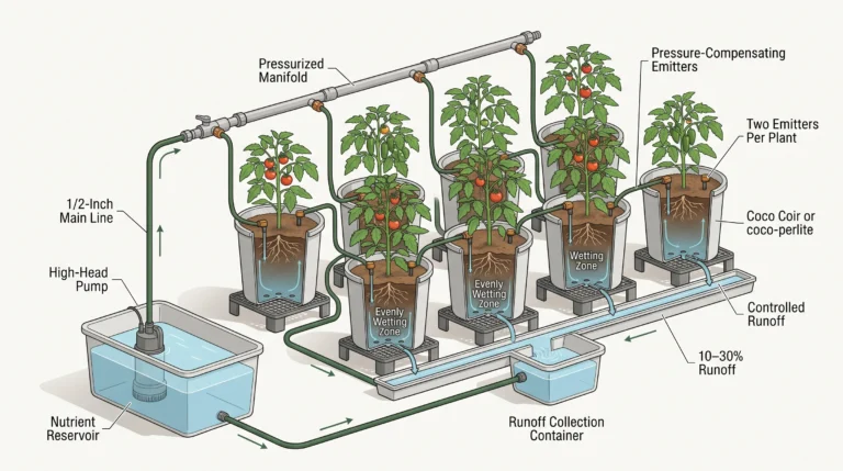
Engineering a hydroponic layout starts with hydraulic calculations. Moving nutrient solutions efficiently requires sizing pumps and pipes to overcome static head and friction losses without causing destructive cavitation.
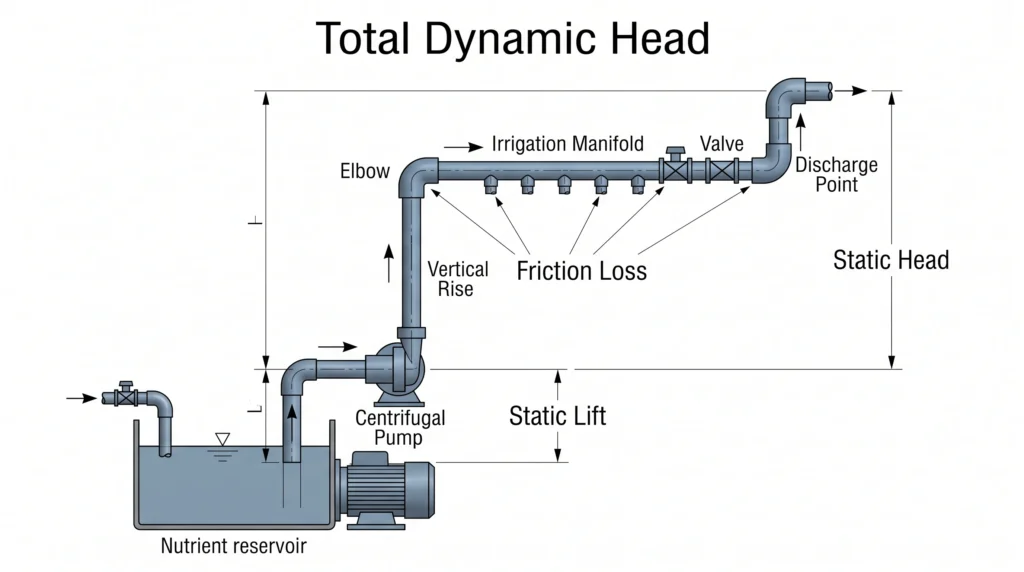
Flow dynamics dictate the survival of a hydroponic crop. Sizing your irrigation delivery network requires calculating the Total Dynamic Head (TDH) of the system. TDH is the total equivalent height that a fluid is to be pumped, taking into account friction losses in the pipe.
TDH = Static Lift + Static Head + Friction Loss
Static lift is the vertical distance from the water line in the reservoir to the pump centerline. Static head is the vertical distance from the pump centerline to the highest discharge point. Friction loss represents the resistance the nutrient solution encounters as it travels through pipes, elbows, and valves.
To calculate friction loss, engineers use the Hazen-Williams equation. Formatted for standard metric applications, the formula is:
h_f = 10.67 * L * (Q / C)^1.852 * d^-4.87
Here, h_f is the head loss in meters, L is the length of the pipe in meters, Q is the volumetric flow rate in cubic meters per second, C is the roughness coefficient of the pipe, and d is the inside pipe diameter in meters. Smooth PVC pipes carry a C-value of 150. Over time, biofilm accumulation drops this coefficient, increasing resistance. Designing with a safety factor of 1.2 accounts for this degradation.
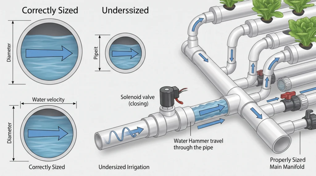
Flow velocity must remain between 1.5 and 2.5 meters per second (m/s). Velocities below 1.5 m/s allow suspended solids and heavy nutrient salts to settle, creating blockages. Velocities exceeding 2.5 m/s generate excessive water hammer (hydraulic shock) when solenoid valves snap shut. Water hammer fractures PVC joints and destroys delicate dosing equipment. Increase your main manifold line size to reduce velocity if your flow rate requirements are high.
Gravity return lines require separate calculations. Drain pipes must be sized to handle at least double the maximum input flow rate to prevent flooding. A standard rule requires a 2% minimum slope (a 2-unit drop for every 100 units of horizontal run) for return manifolds in Nutrient Film Technique (NFT) and Dutch bucket configurations.

- Supreme Aqua-Mag 1200 Pumps are ideal for saltwater or freshwater aquariums and can operate in-line or submerged, with …
- Recommended Tank Size: 150 Gallons
- Operates Submerged or In-Line
- Why it’s necessary: Magnetic drive pumps isolate the motor from the nutrient solution, preventing oil leaks and resisting the corrosive effects of heavy fertilizer salts. They provide consistent high-head pressure suitable for complex manifolds.
- Key Spec: 18-foot max head lift / 1200 GPH flow rate
Component Selection and Material Specifications
Choosing the right materials prevents chemical degradation and catastrophic mechanical failures. Equipment must withstand constant exposure to corrosive salts, acidic pH buffers, and intense ultraviolet light.
Piping materials directly impact nutrient stability. Polyvinyl Chloride (PVC) and High-Density Polyethylene (HDPE) are the industry standards. Schedule 40 PVC handles the low-pressure requirements of most recirculating systems. High-pressure aeroponics requires Schedule 80 PVC or reinforced nylon tubing to withstand pressures exceeding 100 PSI. Never use copper or galvanized steel pipes. Nutrient solutions are highly electrolytic. Heavy metals will leach into the water, causing severe phytotoxicity and rapid plant death.
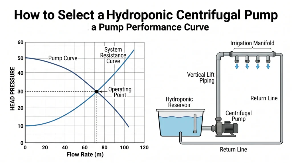
Pump selection requires matching the TDH calculation to a manufacturer’s pump curve. If your system requires 400 gallons per hour (GPH) at a TDH of 8 feet, you cannot buy a pump rated for a maximum of 400 GPH. A 400 GPH pump delivers that flow rate at zero feet of head. At 8 feet of head, its output might drop to 50 GPH. You must read the specific pump curve chart to find a model that delivers 400 GPH at the 8-foot mark. For a deeper breakdown of pump mechanics, review our complete hydroponic pump sizing guide.
Sensors require specific calibration stability features. Industrial pH probes use a double-junction reference design. Single-junction probes fail quickly in hydroponics because heavy fertilizer salts contaminate the reference electrolyte solution. Double-junction probes place a secondary barrier between the reference wire and the nutrient solution, extending the sensor’s lifespan from three months to over a year.
Environmental Control Engineering
The atmosphere inside a grow space dictates the transpiration rate of the crop. Managing temperature, humidity, and airflow ensures the plant can transport water and nutrients from the roots to the leaves.
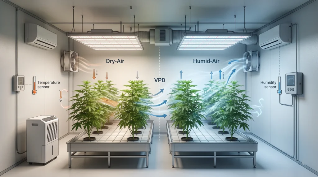
Transpiration is the engine of plant growth. It is driven by Vapor Pressure Deficit (VPD). VPD measures the difference between the amount of moisture the air holds and the maximum amount of moisture the air could hold at a specific temperature. It is a far more accurate metric than Relative Humidity (RH) because it accounts for temperature variations.
To calculate VPD, you first determine the Saturation Vapor Pressure (SVP) and the Actual Vapor Pressure (AVP).
SVP (in kilopascals, kPa) = 0.61078 * e^( (17.27 * T) / (T + 237.3) )
T is the air temperature in degrees Celsius.
AVP = SVP * (RH / 100)
VPD = SVP – AVP
Most vegetative crops require a VPD between 0.8 and 1.2 kPa. When VPD drops below 0.4 kPa, the air is too saturated. Transpiration stops. Roots cease pulling water and calcium from the reservoir, causing tip burn and blossom end rot. When VPD exceeds 1.6 kPa, the air is too dry. The plant closes its stomata to prevent dehydration, halting photosynthesis and halting growth.
HVAC systems must be sized to remove both the sensible heat generated by grow lights and the latent heat (humidity) released by plant transpiration. A mature tomato plant transpires up to 2 liters of water per day. A room with 500 plants introduces 1000 liters of water into the air daily. Dedicated commercial dehumidifiers are required. Standard residential units will freeze up or fail under these massive moisture loads.
Airflow velocity across the leaf canopy should average 0.3 to 0.5 m/s. This breaks the micro-boundary layer of humid air resting directly on the leaf surface, ensuring continuous stomatal gas exchange. Horizontal Air Flow (HAF) fans positioned in a race-track pattern push air efficiently down one side of a greenhouse and back up the other. If managing internal temperatures becomes too costly, specific architectural changes can lower ambient heat. Detailed methods for managing thermal loads are outlined in our passive hydro cooling guide.
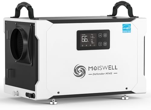
- Specially Designed for Crawlspace: With a sleek horizontal design and compact size of 22.5*14*14.7 inch (L*W*H), Moiswel…
- Heavy-duty Performance with Energy Star Efficiency: This crawlspace dehumidifier is Energy Star certified, ensuring top-…
- Expertly Engineered for Easy Operation: Simply set the desired humidity value, and this commercial dehumidifier will aut…
- Why it’s necessary: Industrial-grade dehumidification is required to manage the massive latent heat load of transpiring plants and prevent botrytis (bud rot) during dark cycles.
- Key Spec: Removes 155 pints of water per day / 115V operation
Nutrient Management Protocols and Chemistry
Precision dosing relies on elemental mass balances. Supplying the correct ratio of macro and micronutrients requires calculating parts per million based on the molecular weight of the fertilizer salts.
Plants absorb elements as individual ions: Nitrates (NO3-), Phosphates (H2PO4-), Potassium (K+), Calcium (Ca2+), and Magnesium (Mg2+). Commercial growers do not use pre-mixed liquid nutrients. They mix dry agricultural salts into concentrated stock solutions.
Calculating the elemental yield of a dry salt requires stoichiometry. Consider Calcium Nitrate, Ca(NO3)2. You want to provide 150 parts per million (ppm) of Calcium (Ca). The atomic weight of Ca is 40. The molecular weight of the entire Ca(NO3)2 molecule is roughly 164.
The percentage of Calcium in the compound is 40 / 164 = 24.3%.
To find the required mass in milligrams per liter (which is equivalent to ppm), divide the target ppm by the percentage.
150 ppm / 0.243 = 617.2 mg/L.
You need 617.2 milligrams of Calcium Nitrate per liter of water to achieve 150 ppm of Calcium.
You must then calculate the amount of Nitrogen added by this same salt. Calcium Nitrate contains about 15.5% Nitrogen.
617.2 mg/L * 0.155 = 95.6 ppm of Nitrogen.
This Nitrogen value must be subtracted from your total Nitrogen target before calculating your Potassium Nitrate (KNO3) additions. Automating these exact mass balances prevents nutrient lockout. You can verify your exact dosing ratios using our hydroponic nutrient calculator.
Nutrient antagonism occurs when elements are supplied in incorrect ratios. An excess of Potassium directly inhibits the uptake of Calcium and Magnesium. An excess of Phosphorus locks out Iron and Zinc. Keeping these ratios tight requires continuous monitoring. For specific target ranges based on crop types, reference our hydroponic pH and EC mastery guide.
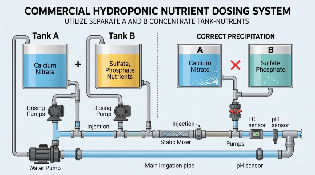
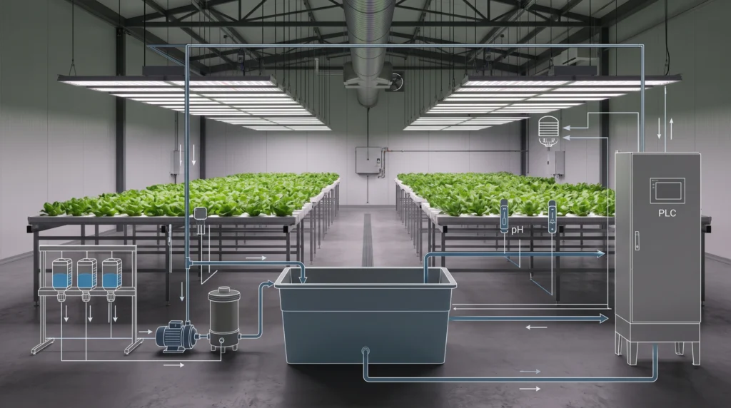
Concentrated stock solutions must be separated into at least two tanks, commonly labeled Tank A and Tank B. Calcium Nitrate must reside in Tank A. Sulfates (like Magnesium Sulfate) and Phosphates (like Monopotassium Phosphate) must reside in Tank B. If these highly concentrated solutions mix directly, the Calcium reacts with the Sulfates and Phosphates to form Calcium Sulfate (gypsum) and Calcium Phosphate (rock dust). These insoluble precipitates fall out of solution, clogging injection manifolds and starving the crop. Formulating dry salts correctly is covered extensively in the hydroponic nutrients guide.
Installation, Commissioning, and Calibration Procedures
Commissioning a hydroponic build transitions the system from static plumbing to an active, pressurized fluid network. Strict baseline testing isolates manufacturing defects and assembly errors before live crops are introduced.
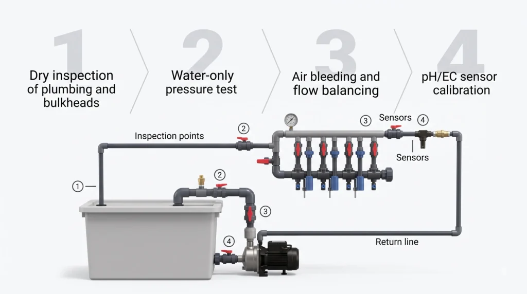
A complete dry-run inspection precedes any water introduction. Verify that all PVC joints are fully cured and that bulkheads are seated tightly against flat surfaces with the rubber gasket positioned on the wet side (inside) of the reservoir.
The wet-commissioning phase requires filling the system strictly with plain water. Do not add nutrients. Turn on the main drive pumps and bleed all air from the manifold lines. Trapped air compresses, causing erratic pressure spikes that blow out drip emitters. Open the flush valves at the end of each irrigation zone to push trapped air and PVC shavings out of the network.
Run the system under full pressure for 48 hours. Mark the water level in the reservoir with a grease pencil. Turn the system off and wait one hour. Measure the drain-down volume. When the pumps turn off, gravity pulls water from elevated pipes back into the reservoir. The reservoir must have sufficient freeboard (empty volume at the top) to contain this backflow without overflowing. If the reservoir overflows during a simulated power outage, you must install check valves on the vertical lift lines or upgrade to a larger tank.
Calibrate all sensor probes during the clear-water flush. pH sensors require two-point calibration using standardized 4.0 and 7.0 buffer solutions. EC sensors require calibration against a known standard, typically 1.41 mS/cm or 2.77 mS/cm. Rinse the probes in distilled water between each calibration liquid to prevent cross-contamination. Calibrate the sensors directly at the injection manifold and then take manual readings at the furthest point in the irrigation line. The EC value at the end of the line must match the manifold reading. A variance indicates that old salts are trapped in the piping or that flow rates are too sluggish to maintain a homogeneous mixture.
Operation, Maintenance, and System Troubleshooting
Sustaining peak performance requires preemptive maintenance schedules. Reactive troubleshooting leads to yield loss. Monitoring equipment degradation and fluid health stops failures before they compromise the harvest.
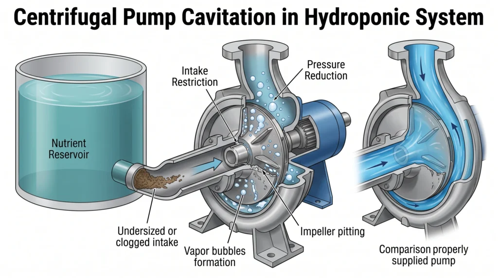
Pump cavitation is a frequent mechanical failure. Cavitation occurs when the pressure at the pump inlet drops below the vapor pressure of the water. The water rapidly boils, forming vapor bubbles. As these bubbles pass through the impeller, they collapse with violent force, pitting the metal and destroying the pump. Cavitation sounds like marbles grinding inside the pump housing. It is caused by restricted intake lines, clogged pre-filters, or pumping water that is too hot. Clean intake screens weekly to maintain adequate Net Positive Suction Head (NPSH).
Biofilm accumulation threatens every recirculating system. Biofilm is a matrix of polysaccharides secreted by bacteria. It coats the inside of PVC pipes, acting as a glue that traps heavy nutrient salts. Over time, biofilm sloughs off in thick sheets, instantly clogging drip emitters and micro-sprayers. Flush irrigation lines with a 3% Hydrogen Peroxide (H2O2) solution or Hypochlorous Acid (HOCl) during the turnaround phase between crop cycles. These oxidizers strip biofilm from the pipe walls without leaving toxic residues. For a complete list of eradication protocols, see our hydroponic troubleshooting guide.
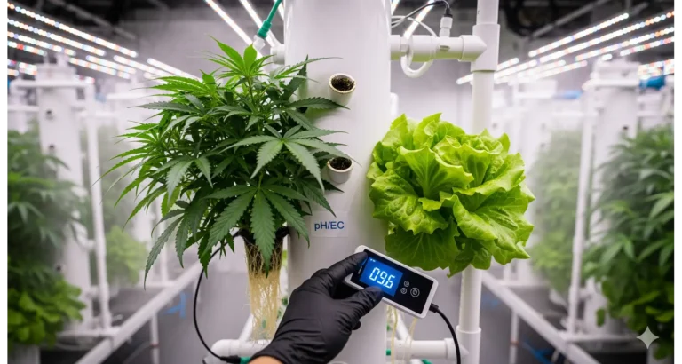
Sensor drift happens constantly. As probes sit in a corrosive nutrient bath, mineral scale builds up on the glass bulb of the pH sensor and the metal prongs of the EC sensor. This scale insulates the sensor, causing it to read sluggishly or report inaccurate data. A pH probe coated in scale might report a pH of 6.0 when the actual solution is 5.2. Clean sensors monthly using a soft brush and a mild acid solution. Recalibrate immediately after cleaning. Discovering the right maintenance rhythm for your specific hardware is mapped out in the hydroponic sensors guide.

- Real-time Monitoring: The Bluelab Guardian Monitor Wi-Fi allows you to monitor your reservoir’s pH, Conductivity, and Te…
- Comprehensive Display and Control: Equipped with built-in Wi-Fi, this device offers monitoring and control. Conductivity…
- Alerts Directly to your Smartphone: The device features high/low pH, temperature, and conductivity alerts, and a non-vol…
- Why it’s necessary: Continuous, inline monitoring of pH, EC, and temperature allows you to spot sensor drift and nutrient imbalances instantly without manually testing the water every day.
- Key Spec: Visual alarms / Plant-safe green LEDs
Commercial Scaling, Economic Analysis, and ROI
Scaling a system from a prototype to a commercial facility shifts the focus from simple plant survival to economic efficiency. Return on Investment (ROI) dictates layout, automation levels, and energy expenditures.
Commercial hydroponic financial modeling splits costs into Capital Expenditure (CapEx) and Operational Expenditure (OpEx). CapEx includes the greenhouse structure, HVAC hardware, racking, plumbing, and automation controllers. OpEx encompasses electricity, fertilizer salts, seeds, growing media, and labor.
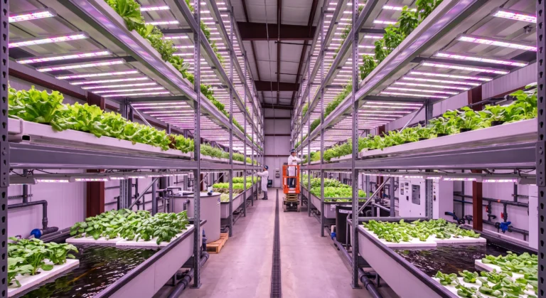
Yield optimization drives profitability. Commercial metrics are calculated in kilograms of harvestable biomass per square meter per year (kg/m²/yr). A standard soil farm might yield 3 to 5 kg/m²/yr of lettuce. An optimized Deep Water Culture (DWC) greenhouse yields 40 to 50 kg/m²/yr. A highly engineered indoor vertical farm can push yields past 100 kg/m²/yr by stacking crop layers.
However, stacking layers exponentially increases OpEx due to artificial lighting requirements. High-intensity LED lighting and the associated cooling loads represent up to 60% of an indoor farm’s operational budget. Conducting a localized energy audit is mandatory. Calculate the cost of producing one mole of Photosynthetically Active Radiation (PAR) using local kilowatt-hour (kWh) rates. If electricity exceeds $0.15 per kWh, indoor vertical farming for low-margin crops like lettuce becomes economically unviable without heavy government subsidies. Review the exact financial breakdown in our hydroponic system upgrades ROI guide.
Labor represents the second-highest OpEx. Automation mitigates this cost. Automated dosing systems eliminate the daily labor of mixing nutrients. Conveyor-belt NFT channels bring the plants to the worker for harvesting, eliminating walking time. Scaling successfully requires analyzing exactly where labor hours are spent and targeting those bottlenecks with mechanical solutions. The harsh realities of commercial economics are broken down further in our vertical farming reality check.
Safety Systems and Redundancy Architecture
Single points of failure destroy crops in hours. High-performance hydroponic networks require N+1 redundancy. For every essential component, a backup must be present and ready to deploy automatically.
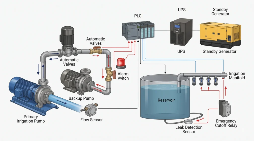
Aeroponic and NFT systems leave plant roots entirely exposed to the air. If a water pump fails, roots dry out and die within 45 to 90 minutes. A backup water pump must be plumbed in parallel to the primary pump. An inline flow sensor monitors the primary line. If the flow rate drops to zero, the controller automatically engages a motorized ball valve and activates the secondary pump.
Electrical outages require Uninterruptible Power Supplies (UPS) and standby generators. A UPS provides instantaneous battery backup, keeping logic controllers, sensors, and small injection pumps online without a millisecond drop in power. Generators take 10 to 30 seconds to spin up and accept the electrical load. The UPS bridges that gap. For off-grid configurations or hybrid resilience, precise battery bank calculations are required. Learn how to size off-grid arrays properly in our solar hydroponics sizing guide.
Flooding is a severe risk in pressurized systems. A burst main line will pump the entire contents of a 500-gallon reservoir onto the floor. Place optical water leak sensors at low points on the facility floor. Connect these sensors to a master cutoff relay. If water touches the sensor, the relay instantly cuts power to the main drive pumps and triggers a digital alert to the facility manager.

- Power Capacity: 1500VA / 900W Pure Sine Wave UPS battery backup provides reliable power protection for your equipment
- Connection Options: Input NEMA 5-15P plug with output featuring (8) NEMA 5-15R outlets for multiple device connectivity
- Automatic Voltage Regulation (AVR): Adjusts high and low voltages to a safe level, helping preserve the life of the batt…
- Why it’s necessary: Provides clean, pure sine-wave battery backup power to keep logic controllers, pH dosers, and environmental sensors online during brownouts while the main generator boots up.
- Key Spec: 900W / 1500VA capacity with Automatic Voltage Regulation
Frequently Asked Questions
How do I calculate the required flow rate for an NFT system?
NFT systems require a thin, continuous film of water. The standard flow rate is 1 to 2 liters per minute, per channel. To size the pump, multiply the number of channels by 2 liters. For a 50-channel setup, you need 100 liters per minute (approx. 1585 GPH) at the discharge height of the manifold.
Why does my reservoir pH constantly rise despite adding pH Down?
Continuous upward pH drift usually indicates high carbonate alkalinity in your source water. Carbonates act as a powerful buffer, neutralizing the acid you add. You must either use a stronger acid (like Phosphoric Acid) to break the carbonate buffer, or switch to Reverse Osmosis (RO) water to strip the carbonates entirely. Rapid pH spikes can also indicate an anaerobic bacterial infection in the root zone.
What is the difference between static head and friction head?
Static head is the physical vertical distance the pump must lift the water against gravity. Friction head is the equivalent resistance caused by water dragging against the pipe walls and changing direction through elbows and valves. Total Dynamic Head (TDH) is the sum of both.
How do I prevent calcium phosphate precipitation in my dosing system?
Never mix concentrated Calcium Nitrate directly with any concentrated Phosphate or Sulfate fertilizer. Keep them in separate A and B stock tanks. Introduce them into the main reservoir or irrigation line independently, allowing massive dilution in the raw water before the ions interact.
Can I run submersible pumps continuously without failure?
Yes, high-quality magnetic drive or direct-drive submersible pumps are designed for continuous 24/7 duty cycles. In fact, turning them on and off frequently via mechanical timers causes more wear on the impeller shaft and motor windings than leaving them running constantly.
What causes pump cavitation in hydroponic systems?
Cavitation occurs when the pump intake is restricted, creating a vacuum that causes the water to boil into vapor at room temperature. Clean the intake pre-filters, ensure the intake pipe diameter is larger than the discharge pipe, and ensure the water temperature remains below 75°F (24°C).
Expand Your Engineering Toolkit
Translating engineering theory into high-yield harvests requires the right operational blueprints. Utilize our massive database of design formulas, CAD layouts, and equipment spec sheets in our tools and resources hub. Whether you are mapping out a small-scale gravity-fed reservoir or engineering a commercial multi-zone dosing skid, precise data drives success. To explore step-by-step schematics for putting these principles into practice, start with our comprehensive DIY hydroponic systems guide. Build it right the first time, scale efficiently, and let the math dictate your yields.
Build smarter: For the full collection of system blueprints, channel layouts, and engineering builds, browse the Growing Systems Hub.

Continue Your Learning Journey